EasyManuals Logo

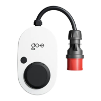
go-e Gemini flex User Manual

go-e Gemini flex
34 pages
To Next Page IconTo Next Page
To Previous Page IconTo Previous Page
Page #18 background imageLoading...
Page #18 background image
1818
9. Commissioning/charging
3.
2.
Ready to charge
The go-e Charger is ready for operation. The
number of blue LEDs corresponds to the set
charging current.
Five predened charging levels can be selected
via the but ton.
1 LED = 1 A
Gemini ex 11 kW = 6 A - 16 A
Gemini ex 22 kW = 6 A - 32 A
1.
Start of the charger
The go-e Charger performs a self-test during
initial start-up or after a restart, during which
the LEDs light up in rainbow colours.
Plugging in the charger
Connect the go-e Charger Gemini ex directly to
a red CEE socket or to a suitable socket using an
original go-e adap ter.
Gemini ex 11 kW = 16 A
Gemini ex 22 kW = 32 A

Other manuals for go-e Gemini flex

Questions and Answers:

Question and Answer IconNeed help?

Do you have a question about the go-e Gemini flex and is the answer not in the manual?

go-e Gemini flex Specifications

General IconGeneral
Connector TypeType 2
Product TypeWallbox
RFIDYes
MID MeterYes
Protection ClassIP54
ConnectivityEthernet
CompatibilityAll EVs with Type 2 connector
Input Voltage400 V AC
Output Voltage400 V AC
Dimensions350 x 220 x 110 mm

Related product manuals