Terminals +, and Malla (shield) are duplicated for easiest cascade installation of parallel–
monitors or telephones. If the first monitor is not placed on the connector, cascade units
will not be powered.
D
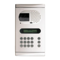
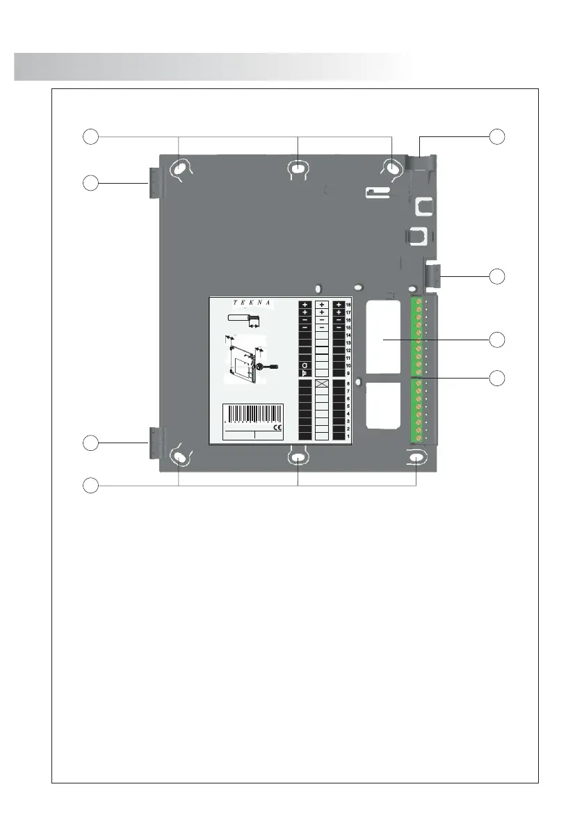
escription of the RCTK-PLUS
monitor connector.
a. Wall attachment hole (x6).
b. Monitor attachment hook (x2).
c. Vertical wiring input.
d. Attachment clip.
e. Wiring input hole.
f. Installation terminals:
positive, .negative (18Vdc)
video signal coaxial input.
coaxial shield.
video signal coaxial output.
audio communication.
digital communication.
door bell push button input.
intercom.
(negative) o (max. current 250mA).utput for additional call repeater
input for external door release push button.
2nd camera activation .(negative) output for (max. current 50mA)
optional device activation .(negative) output for (max. current 50mA)
twisted pair video signal.
+, –:
Vin :
Malla:
Vout :
A :
D :
HZ- :
INT :
SA :
:AP+
2C :
A1 :
Vp, Mp :
MONITOR INSTALLATION
50
MONITOR CONNECTOR DESCRIPTION
49
F
ix the monitor connector to the wall.
F
ix the monitor.
Avoid to place the monitor near to heating sources, in dusty
locations or smoky environments.
To install the monitor directly over the wall, drill two holes of
Ø6mm. and use the supplied screws.
The upper part of the monitor connector must be placed
at 1,60m. height roughly. The minimum distance
between the monitor connector and the closest object
must be 5cm.
Place the monitor at right angles to the
connector and align the attaching holes of the
monitor with the attachment hooks of the
connector, as it is shown on the drawing.
Lock out the monitor. Press the right side till the
attachment clip locks the monitor firmly.
To disassemble the monitor from the connector,
use a plain screwdriver to release the
attachment clip. Remove the monitor from the
connector, with special attention do not falls.
a
a
b
b
f
e
d
c
90
50mm.
50mm.
Colocar la parte superior de la regleta a 1,60m. del suelo.
Place the top part of the monitor connector at 1,60m.
from the floor.
Distancia mínima entre los laterales de la regleta y
cualquier objeto debe ser de 5cm.
Presionar para abrir.
Press to open.
CO DE 117 420 80
RE F
RC T K- P LUS
LO TE
IM P 90 3 012
Max.
5mm
CABLE
Max. pelado del cable.
Max. peeled cable.
Max. câble dénudé.
Max. aanstrip lengte.
Vin
Vout
Malla
Shield
MP
Malla
Shield
CETK590
A
D
INT
SA
CTO
OA1
VP
OA1
( )
*
( )
*
( )
*
18
17
16
15
14
13
12
11
10
9
8
7
6
5
4
3
2
1
Vin
Vout
Malla
Shield
HZ-
INT
SA
AP+
2C
VP
MP
Malla
Shield
A1
PLUS
A
D
Vin
Vout
Malla
Shield
HZ-
SA
2C
A1
VP
MP
MP
Malla
Shield
VP
 Loading...