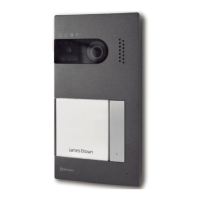
POWER SUPPLY INSTALLATION
D
etail of installationFA-805 .power supply
To install the in the wall, drill two holes whose diameterpower supply
6mm .is and insert the plugs Fix the by means ofpower supply
the proper s.screw
The can be installed on apower supply DIN 46277
guide rail (6 elements) .pushing it slightly
To remove the from the guide rail,power supply
put a flat screwdriver under the edge and
.prise it open as shown in the picture
Install the in a dry sheltered place.power supply
Remember that, according to the regulations in force,
it is necessary to protect the by means ofpower supply
a magnetothermic switch.
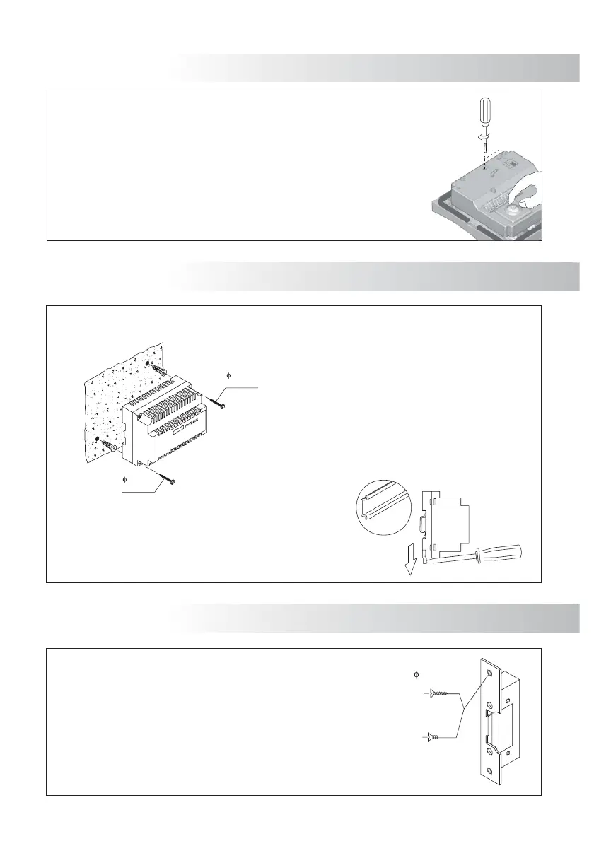
LOCK RELEASE INSTALLATION
D
etail of the lock release installation.
If the lock release must be installed on a metal door,
use a 3,5mm drill and thread the hole.
,If it must be installed on a wooden door
use a 3mm drill.
.WARNING: See connection diagrams on page 69
DIN 46277
44
If, when using the device, audio volume is inadequate, it is necessary to carry out
some adjustments, as shown in the picture.
The camera is equipped with an horizontal and vertical orientation device.
If orientation is not correct, change it.
Fix the to the box by means of the proper screwsdoorpanel embedding .
F
inal adjustments
DOOR PANEL INSTALLATION
3,5 x 45
DIN-7971
3,5 x 45
DIN-7971
M 4 x 8
3,5 x 25
DIN-7972
DIN-963
DOOR PANEL INSTALLATION
D
oor panel configuration.
The is provided with microswitches and(SW1)door panel
a jumper in its rear part; Their functions are(JP1)
described below.
When this switch is ON, the can (audiodoor panel autoswitch-on
and/or video communication without any call). In buildings with
several , just activate this function in one of them. Indoor panels
systems equipped with a general this function can bedoor panel,
activated in one of each detached house.door panel
Select monitors and telephones programmingON for . Once the
programming progress is finished return the switch to OFF position.
Page describes monitors method; while pages51-52 59program
and describes telephones method.63 program
Select in case of a main Each system must beOFF door panel.
equipped with just one main all the others must bedoor panel; slave
door panels door panel,(ON). In systems provided with a general
one of each house will be configured as maindoor panel door panel.
Select if the is provided with a camera Select if itOFF . ONdoor panel
has no camera.
With a general select ON to program the backbonedoor panel,
installation. Once the programming progress is finished return the
switch to OFF position.
Page describes the method64 program .
Equip the installation with a communication resistance. To ensure a
correct operation, this resistance must be activated only in the door
panel which is the nearest to the backbone installation or in the
general door panel (if one exists). If any RD-Plus/Uno SE repeater is
used, it must be deactivated in the door panels behind it.
*Factory value
1
2
3
1
2
3
It allows the connection of an alternative current
door opener; page shows the connection69
diagram.
It allows the connection of a direct current door
opener; page shows the connection69
diagram.
SW1
JP1
43
 Loading...