40
O Microprocessed video withsystem 3 wires+coaxial installation or 4 wires+twisted pair
installation Uno technology.
without making any change on the doorpanel.
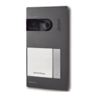
O IP-44 IK-09.sealed and anti-vandaldoor panel
O Compatible with monitors and telephones Uno and PlusTekna Plus .
O Compatible with electronic audio systems or video systems with four common wires, three
wires+coaxial or four wires+twisted pair installations.
O Unlimited number without using commutation units.door panel
O Combinable , .with code general entrance up to 250 internal housespanels
O Maximum distance between and monitor: 200mdoor panel .
O Distance from door panel to last monitor is largest than 200 m, it will be necessary to use the digital
repeater RD-Plus/Uno SE.
O Phone tones to confirm call and busy line.
O Temporized door opening for three seconds.
O Direct current or alternative current lock release activated by means of a relay.
O Up to two monitors and one phone in each house without extra power supply.
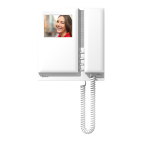
O In monitorsTekna Plus :SE Color (for installation Plus/ Uno).
wPrivacy on audio and video communications.
w"Autoswitch-on" function.
w"Video-spy" function with the communication channel remaining free.
wCall volume lcontro : maximum, medium and minimum.
wIntercommunication function with other monitor o telephone of the same apartment.
wInput for external door bell push button.
wNegative o (maximum current 250mA).utput for additional call repeater
wCall to a master and slave porter's exchange. Panic call to the porter's exchange.
wDip switches for quick programming mode monitor.
wActivation of two auxiliary devices: secondary telecamera, courtesy light, ...
w"Doctor mode" function (automatic door opening).
wInput for external door release push button.
wBrightness and co control.lor
wDifferent call reception tones depending where the call is comming from: door panel, door bell
push button, intercom., porter's exchange.
SAFETY PRECAUTIONS
SYSTEM CHARACTERISTICS
O Install or modify the equipment .without the power connected
O The installation and handling of these equipments must be performed by .authorised personnel
O The entire installation must be at least . away from any .40 cm other installation
O With power supply:
wDo not use excessive force when tightening the connector screws.
wInstall the power supply in a dry and protected place without risk of drip or water projections.
wAvoid to place it near to heating sources, in dusty locations or smoky enviroments.
wDo not block ventilation holes of the unit so that air can circulate freely.
wTo avoid damage, the power supply has to be firmly fixed.
wTo avoid an electrical shock, neither remove the protection cover nor handle the connected wire in
the terminals.
O With monitor, telephones and distributor:
wDo not use excessive force when tightening the connector screws.
wInstall the power supply in a dry and protected place without risk of drip or water projections.
wAvoid to place it near to heating sources, in dusty locations or smoky enviroments.
wDo not block ventilation holes of the equipments so that air can circulate freely.
O Remember, the installation and handling of these equipments must be performed by authorized
personnel and in the absence of electrical current.
O Do always follow the enclosed information.
Continue
INTRODUCTION
39
Introduction........................................39
Index................................................. 39
Starting recommendations................... 39
Safety precautions...............................40
System characteristics -.....................40 41
System operation.................................41
Very important note.......................... 41
Door panel installation.............................
Embedding box positioning................ 24
Door panel configuration...................43
Final adjustments..............................44
Power supply installation.......................44
Lock release installation....................... 44
Tekna Plus SE ..............................Monitor
Description...................................... 45
Function buttons............................... 46
SW2 dip switch (quick prog. mode)......47
RJ-45 connector................................47
End of line resistor............................. 48
EL562 Module..................................48
Monitor connector............................ 49
Monitor installation........................... 50
Programming 2..............................51-5
Quick programming......................... 52
Programming (monitor functions)...53-56
T- 40 Uno5 SE .........................telephone
Description unction push button& f ...... 57
T ....................... 58elephone installation
Programming................................... 59
T- 40 Plus Telephone5 ...............................
Description................................. 60-61
Function push buttons........................61
Telephone installation........................62
Programming................................... 63
Programming backbone code...............64
Installation diagrams...............................
Video system with coaxial cable..... 65-66
Video system with twisted pair -........ 67 68
D.c. and a.c. lock release................... 69
External button to open the door.......... 69
Sections charts..................................69
Optional connections..............................
Aux. device activation Tekna Plus SE.....70
2nd camera activation.......................71
External lock release T 40Plus5 ............71
External lock release Tekna Plus SE...... 71
Intercom 7.......................................... 2
Aux. devices activation T 40Plus5 .........73
Door bell push button connection........73
Troubleshooting.................................. 74
Compliance....................................... 75
INDEX
First of all we would like to thank and congratulate you for the purchase of this product manufactured by
Golmar.
The commitment to reach the satisfaction of our customers is stated through the ISO-9001 certification
and for the manufacturing of products like this one.
Its advanced technology and exacting quality control will do that customers and users enjoy with the
legion of features this system offers. To obtain the maximum profit of these features and a properly wired
installation, we kindly recommend you to expend a few minutes of your time to read this manual.
STARTING RECOMMENDATIONS
O Do not use excessive force when tightening the power supply connector screws.
O The entire installation must be at least . away from any .40cm other installation
O Before to connect the system, check the connections between door panel, monitors, telephones, and
the transformer connection. Do always follow the enclosed information.
O Each time the power supply is restarted, or after a modification, the system will remain blocked during
45 seconds.
O Always use coaxial cables, (see page ).RG-59 B/U MIL C-17 or RG-11 69 Never use coaxial
antenna cable. Golmar RAP-5130In installations no longers than 100m., cable can be used.
 Loading...