OPTIONAL CONNECTIONS
A
uxiliary devices activation with Tekna Plus monitor.SE
The use of a FA-805 power supply ( TF-104 transformer (maximummaximum current 0,8A) or
current 1,5A) will be necessary to activate a second lock release.
A
_
+
D
Malla
V
in
V
out
CN4
Tekna Plus SE
220 Vac/
1.8A max.
SAR-12/24
P
N
IN IN
NC NA C
( )
*
The neutral supply from the stairs light will be wired through the relay contacts SAR-12/24, the maximum current for stairs
light will be 1.8A.
( )
*
To distributor/
door panel.
To stairs light
push button
Lock release
Vac.
Main
SAR-12/24
IN IN
NC NA C
A1
A
_
+
D
Malla
V
in
V
out
CN4
Tekna Plus SE
To distributor/
door panel.
A1
To activate auxiliary devices the use of a SAR-12/24 relay unit will be required. If this device is shared
for all the Tekna Plus monitors, link their A1 terminal and use just one relay unit. In case that each
monitor has its own application use a SAR-12/24 relay unit for each monitor and don't link the A1
monitor terminals.
To activate this function, press monitor push button at any moment with no dependence of the
handset position.
Usual applications are the activation of stairs light, second lock release, ...
FA-805 or T 104F-
SEC
PRI
230110 0
-
+
~~
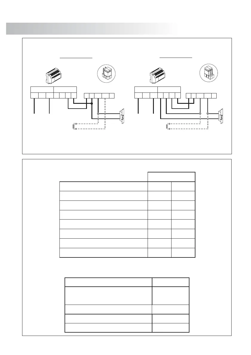
INSTALLATION DIAGRAMS
L
ock release connection.
In order to open the door in any moment by means of an external button, connect the button
between terminals and as shown in the diagram.door panel 'CV1' 'CV2’
This function allows the user to exit the building without using any key.
d.c. lock release
a.c. lock release
CV1
CV2
-
PVS-295SE
FA-805
SEC
PRI
-
~~
230 110 0
Main
D
CV1
CV2
-
PVS-295SE
D
1
2
3
1
2
3
JP1
JP1
+
FA-805
SEC
PRI
+
-
~~
0110230
Main
+
+
1,00mm² 1,50mm²
0,25mm² 0,25mm²
Power supply / Door panel / Lock release
50m.
Sections up to
100m.
, +
+, , CV1, CV2–
CAT-5
RG-59
V , V
in+ out+
V , V , V M
in+,- out+,- p,d, p,d
RG-59
CAT-5
* *
1,00mm² 2,50mm²
~
Door panel / Monitor
100m. 200m.
A , A , A, D
in out
_
(Coaxial)
(Twisted pair)
1,00mm² 2,50mm²
S
ections chart.
C
oaxial cable characteristics RG-59 B/U MIL C-17.
Core max. electrical resistence to 20ºC
Copper core
Copper shield
ELECTRICAL CHARACTERISTICS
Nominal capacitance
Characteristic impedance
VALUES
75 3 W
+
-
<67pf/m
*
<158 /KmW
<10 /KmW
_
_
_
Velocity of Propogation
_
>66,6 %
69
70
 Loading...