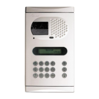
O
ne or more accesses, alternative current
lock release and twisted pair.
Main
A
+
_
D
V
p
M
p
A D
_
+
D6L-Plus/2H
EL562
JP1
V
p
M
p
A D
_
+
EL562
JP1
V
p
M
p
A D
_
+
EL562
JP1
V
p
M
p
A D
_
+
EL562
JP1
JP1
A
A
D
D
CT
+
+
V
pi
V
d1
M
pi
M
d1
_
_
A
D
CT
+
V
d6
M
d6
_
A D+
V
po
M
po
_
FA-805
SEC
PRI
+
-
~~
230 110 0
DAinAoutVin-Vin+Vout- Vout+ + CV2CV1
--
PVS-295SE
67
Vca.
Lock release
S
M =Master.
S =Slave.
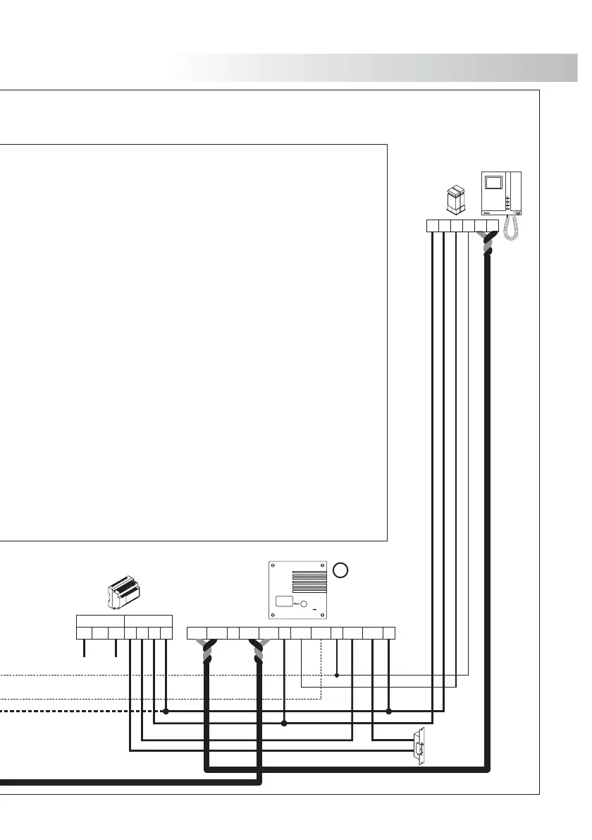
INSTALLATION DIAGRAMS
Main
Example of cascade connected devices.
Remove jumper of all EL562 circuitsJP1
( ),from monitors see page 48
except from the one in which the
.twisted pair end is located
Example of distribution connected devices.
Remove the end of line jumper from all the
distribu (JP1)tors and all EL562 (JP1) from
monitors except from those ones in which,
the twisted pair cable end is located (without
using output).
If your device is equipped with just one door panel,
.do not consider connections to other door panels
If your device is equipped with more than one door panel,
.connect the other as shown in the picturedoor panels
IMPORTANT NOTE
When using a d.c. lock release, just 2 wires are
needed between power supply and door panel.
Refer to diagram on page .69
FA-805
SEC
PRI
+
-
~~
0110230
DAinAoutVin-Vin+Vout- Vout+ + CV2CV1
--
PVS-295SE
V
p
M
p
A D
_
+
EL562
JP1
68
Vca.
Lock release
M
Tekna Plus SE
RCTK Plus
 Loading...