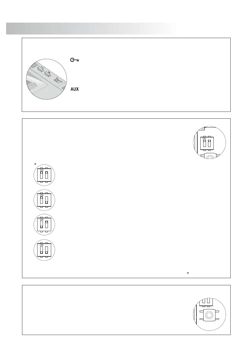
D
escription of configuration dip switch.
D
escription of programming push button.
Factory default
"Autoswitch-on" mode: switches 1 and 2 to ON.
With the handset off the cradle, allows to stablish audio communication with the
door panel that has been configured with the autoswitch-on function. This
function is disabled if a communication is already established.
"PA" output mode: switches 1to ON and 2 to OFF:
Regardless of the handset , it activates the "PA" telephone output.'s position
"C " mode: switches 1 to OFF and 2 to ON.all to a slave porter's exchange
With the handset off the cradle, allows to call to a porter's exchange that it is
configurated as slave.
" " mode: switches 1 and 2 to OFF.
Intercommunication
With the handset off the cradle, allows to make an intercom call between two units
of the same apartment.
The P3 programm push button is located in the top part left of the circuit,it is
accessed by opening the telephone. Allows to telephone enter in programming
mode with the door panel, (see programming process on page ).63
IMPORTANT: Select before programming the telephone.the auxiliary function push button mode
The SW1 configuration dip switch is located in the top part left of the circuit,it is
accessed by opening the telephone and allow the next operation modes for the
auxiliary function push button:
F
.
unction push buttons
If the handset is on the craddle sends a panic call to the porter's
exchanges that have enabled the reception of this type of call. If not,
allows to call to the master porter's exchange. During call reception
and communication progresses allows the lock release activation.
Auxiliary function push button, setting SW1depending on in the dip
switch will realize one of the following functions: Autoswitch-on, "PA"
output, call to a slave porter's exchange and intercommunication.
TELEPHONE DESCRIPTION TELEPHONE INSTALLATION
62
61
F
ix the telephone to the wall
.
It is necessary to open the telephone for wiring and fixing
purposes To open the telephone, insert a plain screwdriver
.
into the slots and gently lever as shown in the drawing.
Pass the installation wires through the corresponding hole and connect
them as shown on the installation diagrams lose the telephone as
. C
shown on the picture Once the telephone is closed, connect the.
handset using the telephone cord and put it on the cradle.
Avoid placing the telephone near sources of heat, in dusty
locations or smoky environments The telephone can be
.
fixed using an electrical embedding box or directly on the
wall, as shown on the picture If the telephone will be
.
installed directly over the wall, drill two holes of Ø6mm on
the specified positions, using 6mm wall plugs and Ø3.5 x
25mm screws
.
 Loading...