Repair
30 3A0590R
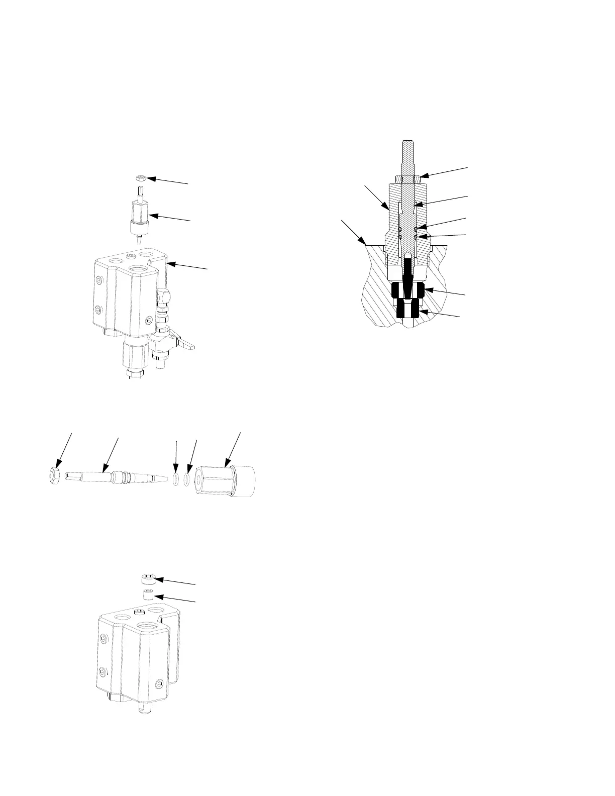
Remove Restrictor
12
16
15
13
14
r_258987_3a0590_5a
1. Note number of turns from open to closed position.
Remove restrictor housing (15) from manifold (1).
2. Place restrictor housing (15) in a vice and remove
nut (16).
3. Unscrew stem (12) clockwise
and remove from
restrictor housing (15).
4. Remove and replace o-rings (13, 14).
5
. Remove set screw (11) and seat (10) from manifold.
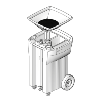
Assemble Restrictor
10
11
1
13 (black)
14 (white)
12
15
16
r_255684_256980_312749_12a
1. Insert seat (10) with larger tapered end facing up in
manifold (1).
2. Apply blue thread lock to external threads to set
scr
ew (11) and install in manifold.
3. Install o-rings (13, 14) and insert stem (12) into
restrictor housing (15). Turn stem (12)
counter-clockwise until in open position.
4. Loosely install lock nut (16) on stem (12).
5. Tighten restrictor housing (15) into manifold (1).
6. Tighten stem (12) down until it bottoms on seat (10).
Then back stem out to previously noted position or
two full turns and lock in place with lock nut (16).
For high volume or high viscosity “B” side applications,
the restrictor parts can be replaced by a high pressure
3/4 npt plug.