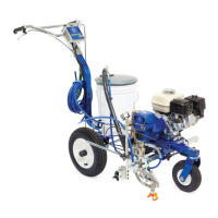
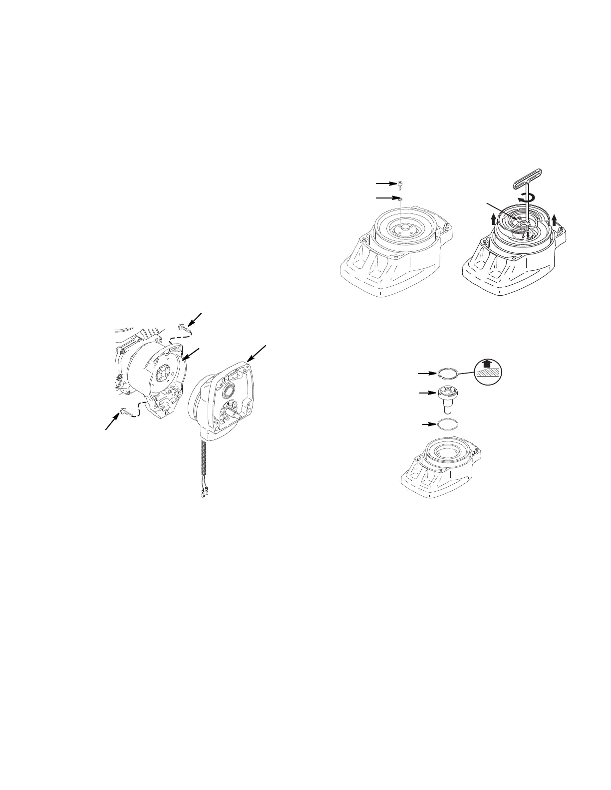
Pinion Assembly/Clutch Armature/Clamp
3A4587D Operation, Repair, Parts 27
Pinion Assembly/Clutch Armature/Clamp
Pinion Assembly/Clutch
Armature Removal
Pinion Assembly
If pinion assembly (44) is not removed from clutch hous-
ing (45), do 1. through 3. Otherwise, start at 4.
1. Perform Pressure Relief Procedure, page 9.
2. Remove drive housing; page 26.
3. Disconnect clutch (+) and clutch (–) connectors from
wire harness located under sprayer cart.
4. Remove four screws (34) and pinion assembly (44).
5. Place pinion assembly (44) on bench with rotor side
up.
6. Remove four screws (42) and lock washers (35).
Install two screws in threaded holes (E) in rotor.
Alternately tighten screws until rotor comes off.
7. Remove retaining ring (44d).
8. Turn pinion assembly over and tap pinion shaft
(44c) out with plastic mallet.