CHOKE REPLACEMENT
WARNING
Before doing this procedure, follow the
Pressure
Relief
Procedure
Warning on page
21
to reduce
the risk of a fluid injection injury, splashing in the
eyes or
on
the skin, injury from moving parts, or
electric shock.
309
Refer
to
Fig
25
7.
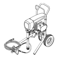
1. Remove the pressure control cover and screws.
2.
Remove the grounding screw (312) and remove the
lead. Loosen the appropriate screw on the terminal
strip (336) and disconnect the
yellow/green choke
lead.
3.
Use
the M8 wrench
to
remove the upper nut and
lockwasher (337,338) on the outside of the pressure
control box.
4.
Remove the old choke (309) and install a new one in
the reverse order
of
disassembly.
-
Fig
25
-
1
VARISTOR REPLACEMENT
WARNING
318
319
A
Refer
to
Fig
25-2
and
25-3.
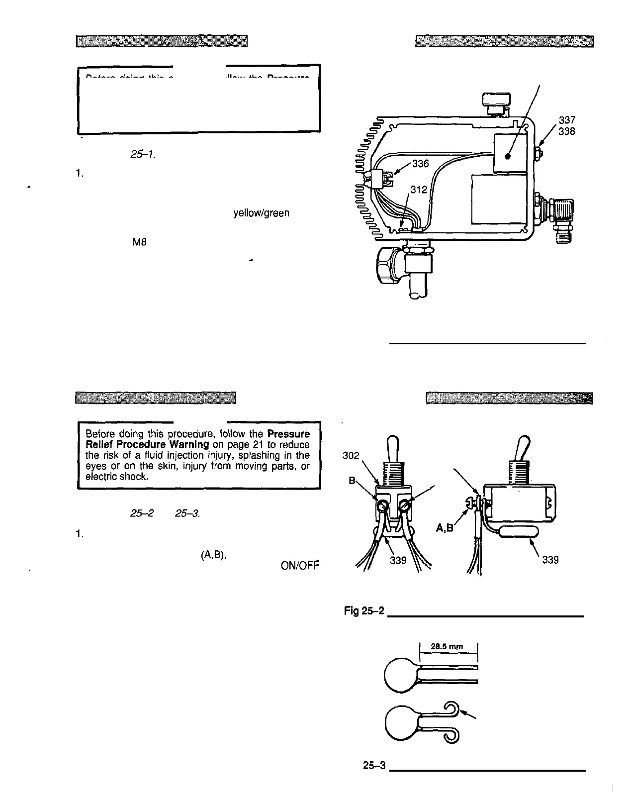
1. Remove the control box screws and cover.
2.
Remove the
two
screws (AB), the wiring harnesses
(318, 319) and the old varistor from the
ON/OFF
switch (302).
FRONT VIEW SIDE VIEW
3. Trim the leads
on
the new varistor (339)
to
28.5 mm.
Turn each lead outward
to
form a
loop
that is large
Fig
25-2
enough for
the
screws
(A,
B)
to
pass through.
4.
Place a wiring harness on each screw, then place a
loop of the varistor leads on each screw and thread
the screws
into
the switch.
5. Wrap the varistor under the switch.
\
FORM
LOOP
LARGE
ENOUGH FOR SCREWS
TO
PASS
THROUGH
Fig
25-3
307670 25