~~
CIRCUIT
BOARD
REPLACEMENT
I
eyes or on the skin, injury
from
moving parts, or
electric shock.
I
Refer
to
Fig
212-1
and
26-2.
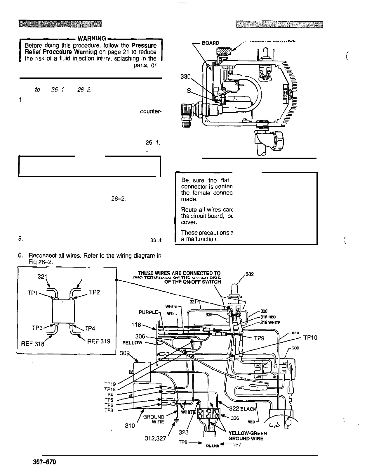
1.
Remove the pressure control cover and screws,
2. Turn the pressure control knob all the way
counter-
tension
on
the board. Also check to be sure only
clockwise
to
the minimum setting
to
release spring
three or four threads of the pressure control knob
shaftareexposed below the pressure adjustment nut
(S).
Back down the nut,
if
necessary. See Fig 26-1.
CAUTION
circuit board while removing or installing it.
Step 2
is
essential
to
reduce the risk of damaging the
*~
3. Disconnect ALL wires from the board, including the
two
heavy black wires. Pay close attention to where
connections are made. See Fig
26-2.
4.
To remove the board from the box, pull out the black
plastic
-
tipped pin (330). Push the bottom of the cir
-
cuit board toward the wall of the box and carefully
slide the board out.
5.
Install the board in the box at the same angle as
it
was removed.
REF
321. REF 320
CIRCUIT
PRESSURE
CONTROL
KNOB
Fig
261
r
CAUTION
Be. sure the flat blade of the insulated male
the female connector when the connections are
connector is centered in the wrap
-
around blade
of
made.
the circuit board, bourdon tube, or pressure control
Route all wires carefully to avoid interference with
cover.
These precautions are essential to reduce the risk of
a malfunction.
7.
Perform the
STALL
PRESSURE
CALIBRATION
starling on page 28,
if
you installed a new board.
i
TPIO
Fig
262
.
LY"
26
307470