STALL
PRESSURE
CALIBRATION
WARNING
USE EXTREME CAUTION WHEN
PERFORMING
THIS CALIBRATION PROCEDURE to
reduce the risk of a
fluid injection injury or other serious bodily injury which can result from component rupture, electric shock,
fire,
explosion, or moving parts.
This procedure sets the sprayer
to
207 bar MAXIMUM NEVER EXCEED
207
bar MAXIMUM WORKING
WORKING PRESSURE. Perform this procedure PRESSURE. Normal operation
of
the sprayer at
whenever the pressure control assembly
is
removed higher pressures could result in component rupture,
and reinstalled or replaced
to
be sure the sprayer is fire or explosion.
properly calibrated.
Use a
new1 5.2 m spray hose rated for at least 207 bar
Improper calibration can cause the sprayer
to
over
-
PRESSURE.
A
used,
under-
plosion.
It
may alsopreventthesprayerfrom obtaining
tUre,
the maximum working pressure, resulting in poor
sprayer performance.
NEVER attempt
to
increase the fluid outlet pressure sembly when the control box cover is removed,
to
re
-
AVOID touching the wire in the pressure control as-
by performing these calibrations in any other way. duce the risk of electric shock.
pressurize and result in component rupture, fire or ex- rated hose
could
develop
a
high
pressure
leak
or
rup-
Service Tools Needed:
NEW 15.2 m,
231
bar, flexible, nylon airless spray
hose, Part No.
210-541
0
-
5000 psi (0
-
350 bar) fluid
-
filled pressure gauge,
Part No.
102-814
New spray tip, size 0.015”
5 gallon pail and water
Mineral spirits
Calibration Setup.
Refer
fig
28-f
and
29-1.
1.
Follow
the
Pressure
Relief
Procedure Warning
on
page
21.
Remove the spray hose and gun. Install a
test hose and connect the hose
to
the sprayer outlet.
0.01
5”
spray tip in the gun. Connect the gun
to
a new
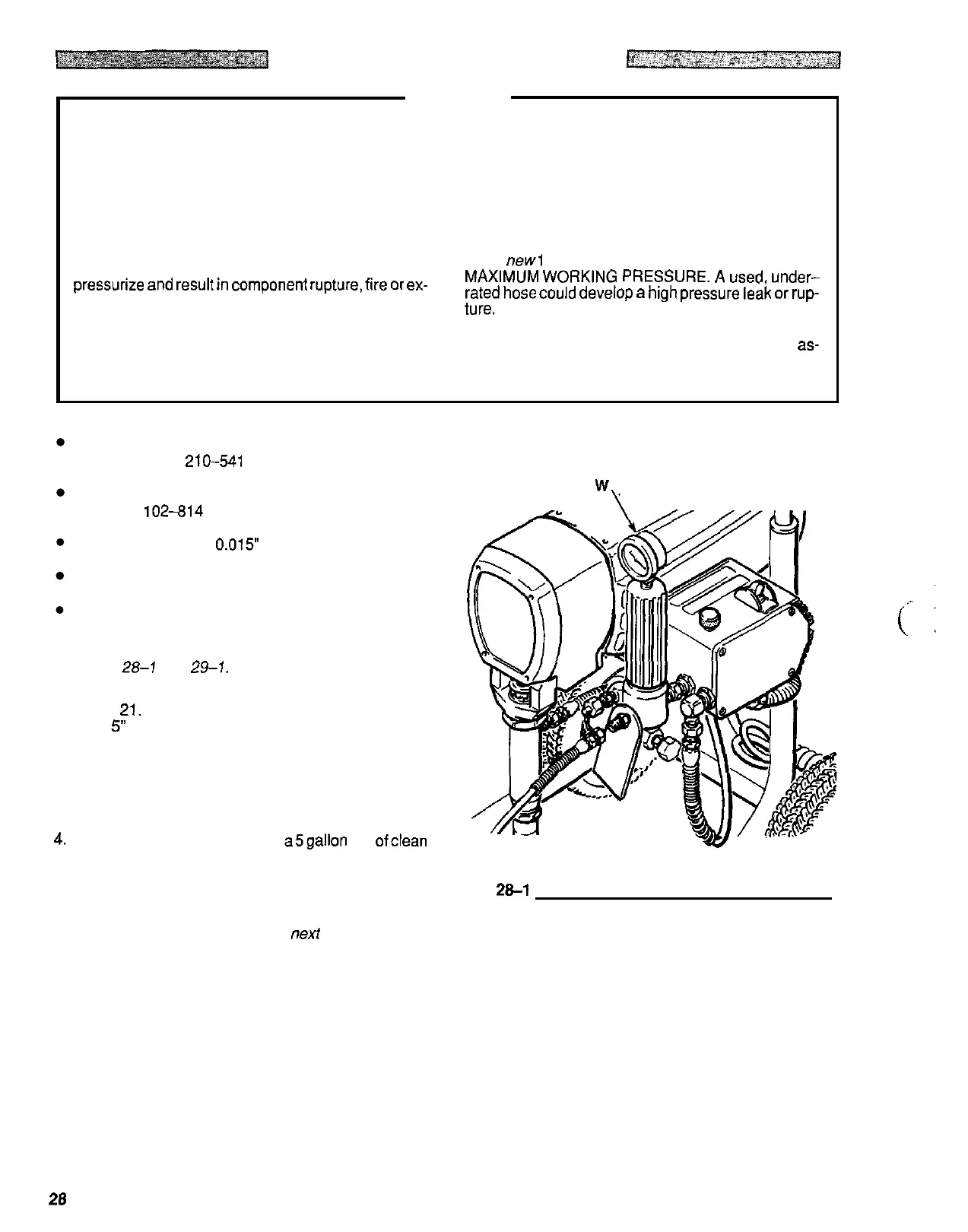
2. Remove the pressure control screws and cover.
3.
Remove the plug from the top of the fluid filter, and
4.
Place the pump suction tube in a5gallon pail ofclean
5. Be sure the gun safety latch is engaged
install the test gauge (W).
water.
Fig
20-1
Procedure continued on next page
28
307670