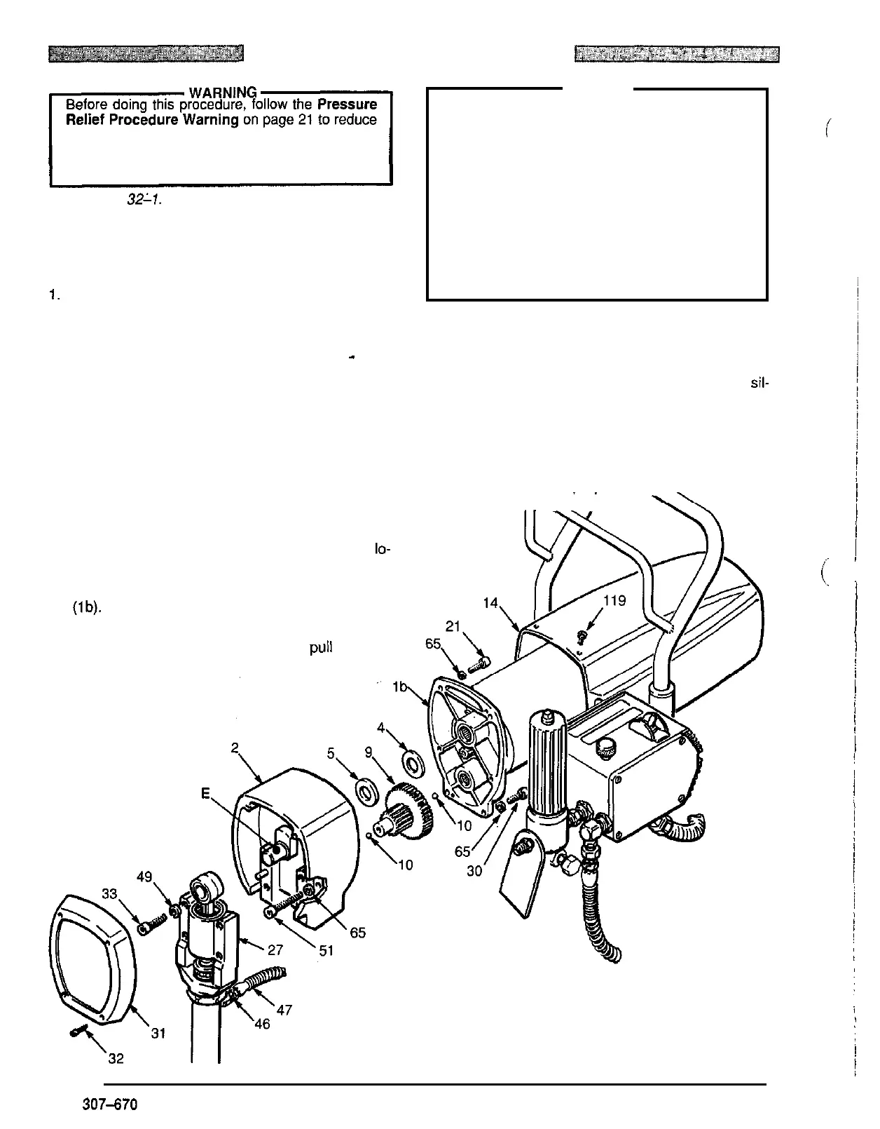
DRIVE HOUSING REPLACEMENT
the risk of a fluid injection injury, splashing in the
eyes or in the skin, injury from moving parts or elec
-
tric
shock. Be sure
to
unplug the sprayer!
Refer
to
Fig
32-17.
NOTE:
Stop the sprayer at the bottom of its stroke to get
the crank
(E)
in its lowest position. To lower it
with a screwdriver.
manually, carefully rotate the blades of the fan
1.
Remove the front cover and screws (31, 32). Re
-
move the six screws (1 19) and motor cover (14).
2.
Disconnect the pump outlet hose (47) from the dis
-
placement pump outlet nipple (46).
-
3.
Use a
5
mm hex key wrench to remove the four
screws
(33)
and lockwashers (49) from the bearing
housing.
4.
Lightly tap the lower rear of the bearing housing (27)
with a plastic mallet to loosen
it
from the drive hous
-
ing
(2).
Then pull the bearing housing and connecting
rod assembly straight
off
the drive housing.
5.
Use a
6
mm hex key wrench to remove the two
screws (51) and lockwashers
(65)
from the recess of
the drive housing, the
two
screws
(30)
and
lo-
ckwashers (65) from the rear
of
the motor front end
bell (Ib) and the two screws (21) and lockwashers
(65)
from the upper rear
of
the motor front end bell
(Ib).
6.
Lightly tap the drive housing
(2)
with a plastic mallet
to
loosen
it
from the front end bell, then pull
it
straight
off.
.
CAUTION
moving the drive housing (2). It is easily damaged
if
DO
NOT
allow the gear cluster (9)
to
fall when re
-
front end bell or the drive housing.
dropped. The gear may stay engaged in either the
DO
NOT
lose the thrust balls (10) located at each
end of the gear cluster (9) or allow them to fall be
-
tween gears. The balls, which are heavily covered
with grease, usually stay in the shaft recesses, but
could be dislodged. If caught between gears and
not removed, the balls will seriously damage the
drive housing.
If
the balls are not in place, the bear
-
ings will wear prematurely.
7. Liberally apply bearing grease to the gear cluster (9).
Check
to
be sure the thrust balls
(1
0)
are in place.
8.
Place the bronze
-
colored washer
(5)
THEN
the sil-
ver
-
colored washer (4) on the shaft protruding from
the big gear in the drive housing (2). Align the gears
and push the new drive housing straight onto the
front end bell and locating pins.
to
reassemble the sprayer.
9. Starting at Step
5
and working backwards, continue
..
Fig 32
-
1
32
307-670
i