~
~~
~~
~~
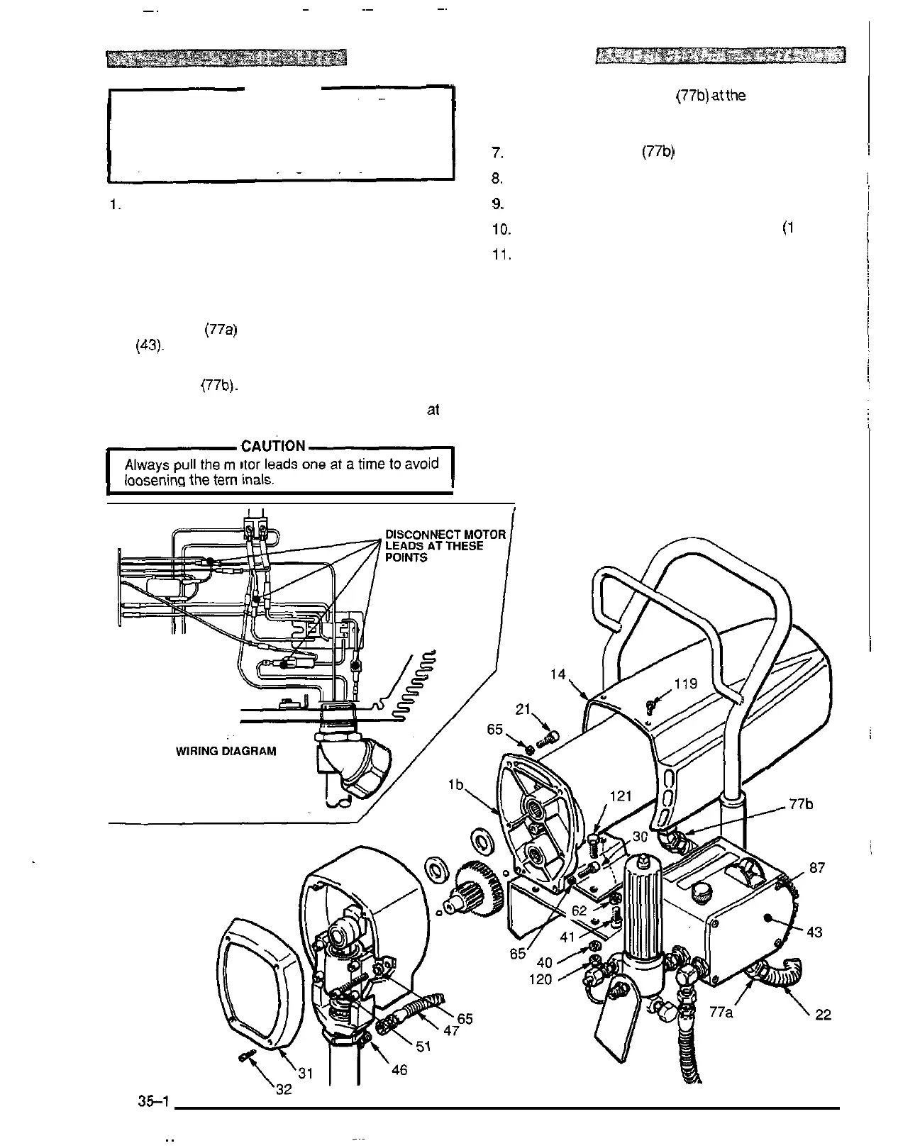
MOTOR
REPLACEMENT
WARNING
Relief Procedure Warning on page 21
to
reduce
Before doing this procedure, follow the Pressure
the risk of a fluid injection injury, splashing in the
eyes or in the skin, injury from moving parts or elec
-
tric shock. Be sure to unplug the sprayer!
1. Disconnect the pump outlet hose (47) from the dis-
placement pump outlet nipple (46).
2.
Remove the pressure control cover and screws and
disconnect the four motor leads. Remove the con-
duit seal from the conduit elbow coming into the con
-
trol
box.
3.
Use an adjustable wrench to loosen the conduit con
-
nector nut
(77a)
at the pressure control assembly
4.
Swing the conduit (22) away from the
-
pressure con
-
5.
Pull
the motor leads through the elbow, one at a
'
time.
(43).
trol elbow (77b).
I
cAuT'oNl
Always pull the motor leads one at a time to avoid
loosening the terminals.
6.
Loosen the connector nut (77b) atthe motor and pull
the conduit (22) away from the motor, then pull the
leads through the conduit, one at a time.
7.
Unscrew the elbow (77b) from the motor.
8.
Pull
the wires through the elbow, one at a time.
9.
Remove the front cover and screws (31, 32).
10. Remove the motor cover (14) and screws
(1
19).
11, Use a 6 mm hex key wrench to remove:
two
screws (51) and washers (65) from the recess of
the drive housing,
two
screws (30) and washers (65) from the lower
rear of the motor front end bell (Ib),
two
screws (21) and washers (65) from the upper
rear of the motor front end bell (1 b).
I
.
I
I
Fig
35-1
307
-
670 35
~~