307-913
16
Pressure
Control Replacement
WARNING
To
reduce the risk of serious injury
, including fluid
injection or splashing in the eyes or on the skin, or
injury from moving parts, always follow the
Pres-
sure Relief Procedure W
arning
on page 6
before checking, adjusting, cleaning, or shutting of
the sprayer
.
Unplug the power supply cord!
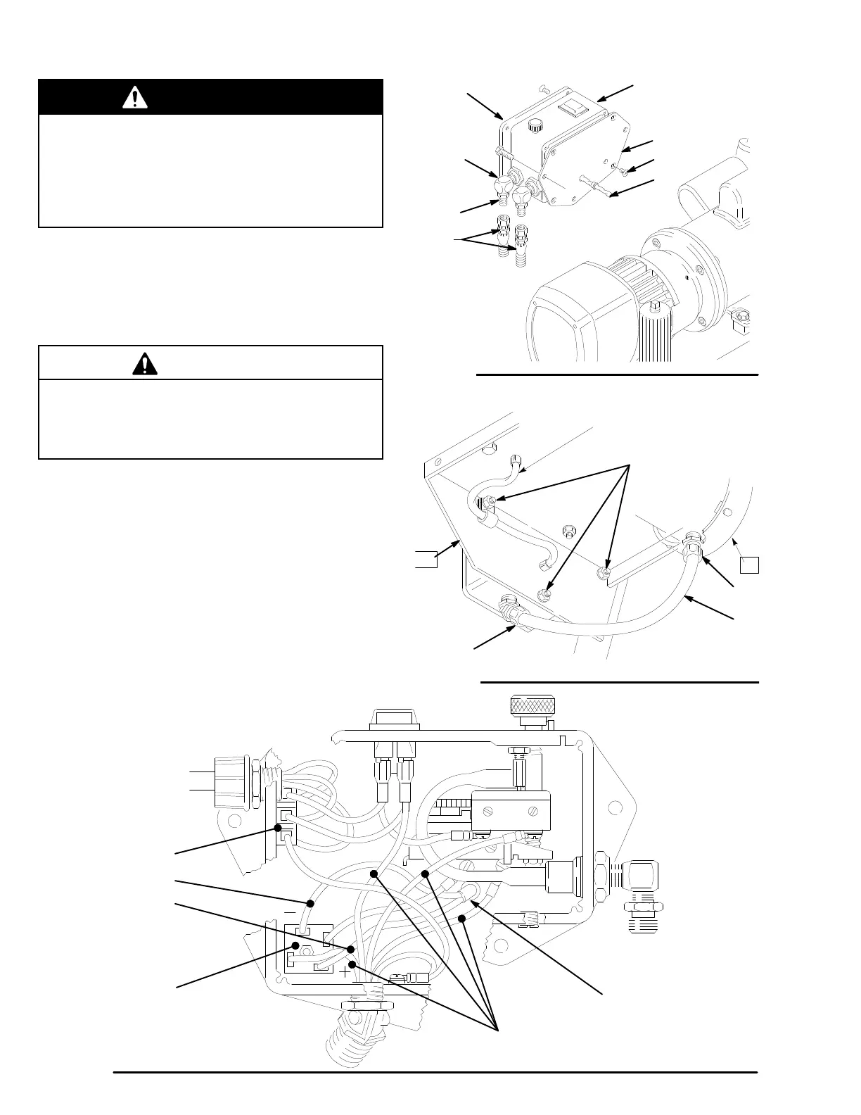
1. Disconnect both hoses (59) at the pressure control
(63). Hold the hex of the nipple (304) firmly with a
wrench
to prevent turning the elbow (303). T
ake note
of the original location of each hose to be sure you
reassemble them correctly at the end of this proce-
dure.
See Fig 13.
CAUTION
Do not allow the elbow (303) to turn when removing
or connecting the hoses. T
urning the elbows can
damage the sensitive bourdon tube in the pressure
control box.
2. Remove
the pressure control cover (76). Disconnect
the + and – leads from the rectifier (310). These
leads
go to the clutch field. Disconnect the five motor
leads. These leads go through the conduit to the
mo
-
tor.
See Fig. 15.
3. Remove the three nuts (61) and lockwashers (9)
from
the capscrews (62). See Fig 14.
4. Unscrew
the nut on the conduit elbow (308). Careful
-
ly
guide the wires through the elbow as you pull the
conduit (94) away from the pressure control.
5. Reassemble. Perform the PRESSURE CONTROL
CALIBRATION PROCEDURE on page 17 before
regular
operation of the sprayer
.
59
63
303 320
302
304
76
0489
90
Fig. 13
VIEW
FROM UNDER ENGINE MOUNTING
62,
9, 61
308
63
1
87
90
94
0490
Fig. 14
–
LEAD
+ LEAD
310
323
MOT
OR LEADS
0485
90
Fig.
15