Drive
Housing
WARNING
To
reduce the risk of serious injury
, including fluid
injection or splashing in the eyes or on the skin, or
injury from moving parts, always follow the
Pres-
sure Relief Procedure W
arning
on page 6
before checking, adjusting, cleaning, or shutting of
the sprayer
.
Unplug the power supply cord!
NOTE:
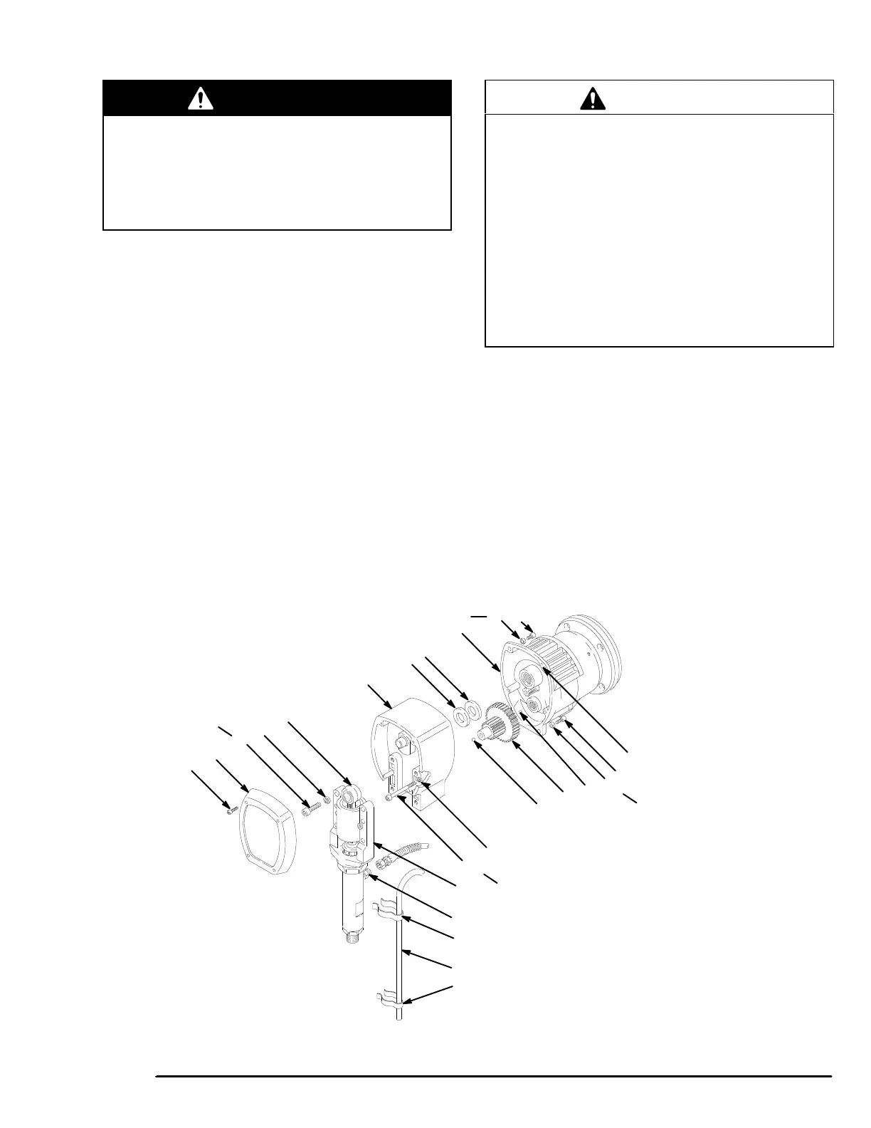
Refer to Fig 21 for this procedure.
Disassembly
1. Remove the front cover and screws (23,68). Re-
move
the spring clips (100,102) and the bypass hose
(101).
2. Disconnect
the pump outlet hose from the displace
-
ment
pump nipple (49).
3. Use
a
hex key wrench to remove the four screws (73)
and
lockwashers (74) from the bearing housing (21).
4. Lightly
tap the back of the bearing
housing (21) with
a plastic mallet. Pull the pump, bearing housing and
connecting rod away from the drive housing as one
assembly.
5. Use
a
hex key wrench to remove the two screws (24)
and lockwashers (11) from the bottom front of the
drive
housing (20). Remove the four screws (10) and
lockwashers (11).
6. Lightly
tap around the drive housing (20) with a plas
-
tic
mallet to loosen it from the pinion housing (19).
CAUTION
Do not drop the gear cluster (18) when removing the
drive housing (20). The gear cluster is easily dam
-
aged. The gear may stop engaged in the drive
housing or pinion housing.
Do not lose the thrust balls (20c or 19d) located at
each end of the gear cluster
, or allow them to fall
between the gears. The ball, which is heavily cov
-
ered with grease, usually stays in the shaft recesses,
but could be dislodged. If the balls are caught be
-
tween the gears and not removed, they will seriously
damage the drive housing. If the balls are not in
place, the bearing will wear prematurely
.
Reassembly
7. Liberally
apply bearing grease (20d,
supplied) to the
gear cluster (18). Be sure the thrust balls (20c and
19d)
are in place.
8. Place
the bronze colored washer (20a)
and then the
silver–colored washer (20b) on the shaft protruding
from
the big bearing of the drive housing (20). Align
the gears and push the new drive housing straight
onto
the pinion housing and locating pins (B).
9. Starting at Step 6, work backwards to reassemble
the sprayer. Or, move ahead to the next section in
this
manual if further service is needed.
10
11
19d
18
20c
11
24
49
68
23
22
20
20a
20b
19
11
10
B
74
73
100
101
102
21
TORQUE
T0
(16–18 N.m)
NOTE: Lightly tighten screws 73,10 and
24 oppositely and evenly. Then
tighten oppositely and evenly
again
to the specified torque.
TORQUE
T0 (5.8 N.m)
T
ORQUE T0 (5.8 N.m)
T
ORQUE T0 (5.8 N.m)
Fig.
21