307-913
8
Operation
WARNING
T
o reduce the risk of serious injury whenever you
are instructed to relieve pressure, always follow the
Pressure Relief Procedure
on page 6.
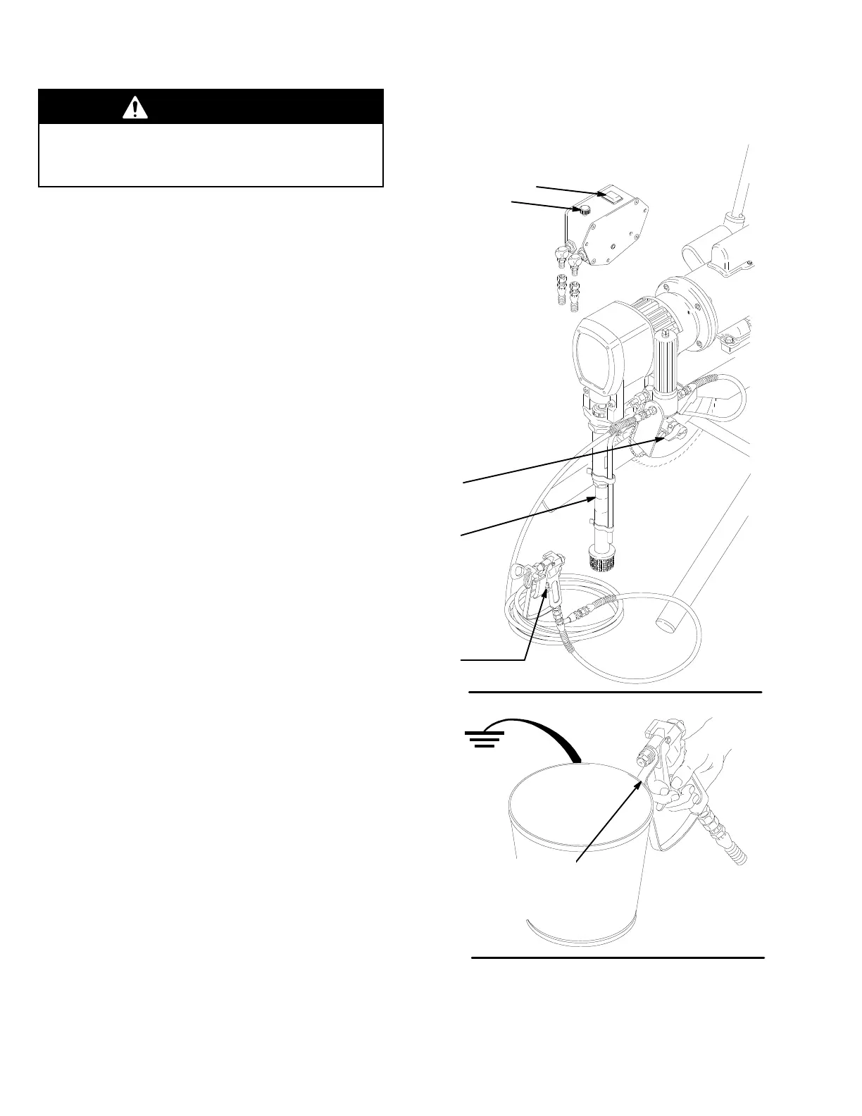
1.
Prime the Sprayer with Paint.
a.
Close the pressure drain valve (C). See Fig. 3.
b.
Don’t install the spray tip yet!
c. Put
the suction tube (D) into the paint
container
.
d. Turn
the pressure adjusting knob (B) all the way
counterclockwise
to lower the pressure setting.
e.
Disengage the gun safety latch (E).
f. Hold a metal part of the gun firmly against, and
aimed into, a grounded metal waste container.
See
Fig. 4. Squeeze the trigger and
hold it open.
T
urn the ON/OFF switch (A) to ON. See Fig 8–1.
Slowly increase the pressure setting until the
sprayer
starts. Keep the gun triggered until all air
is forced out of the system and the paint flows
freely
from the gun. Release the trigger and en
-
gage
the gun safety latch.
NOTE: If the pump is hard to prime, open the pressure
drain valve (C). When fluid comes from the
valve, close it. Disengage the gun safety and
proceed
as in Step 1f, above.
g. Check
all
fluid connections for leaks. If any leaks
are
found,
relieve the pressure
before
tighten
-
ing
connections.
2.
Install the Spray T
ip and T
ip Guard
a.
Be sure the gun safety latch is engaged.
b. Install
the spray tip. If you are using the RAC IV
tip
guard, refer to manual 307–848, supplied with
the
gun, for installation instructions.
KEY
A ON/OFF Switch
B
Pressure Adjusting Knob
C Pressure Drain Valve
D
Suction T
ube
E
Gun Safety Latch
A
B
C
D
E
0482A
Fig.
3
0483
MAINTAIN
FIRM
MET
AL T
O MET
AL
CONT
ACT BETWEEN THE
GUN AND A GROUNDED
MET
AL CONT
AINER
Fig.
4