Setup
1. Connect Hose and Gun
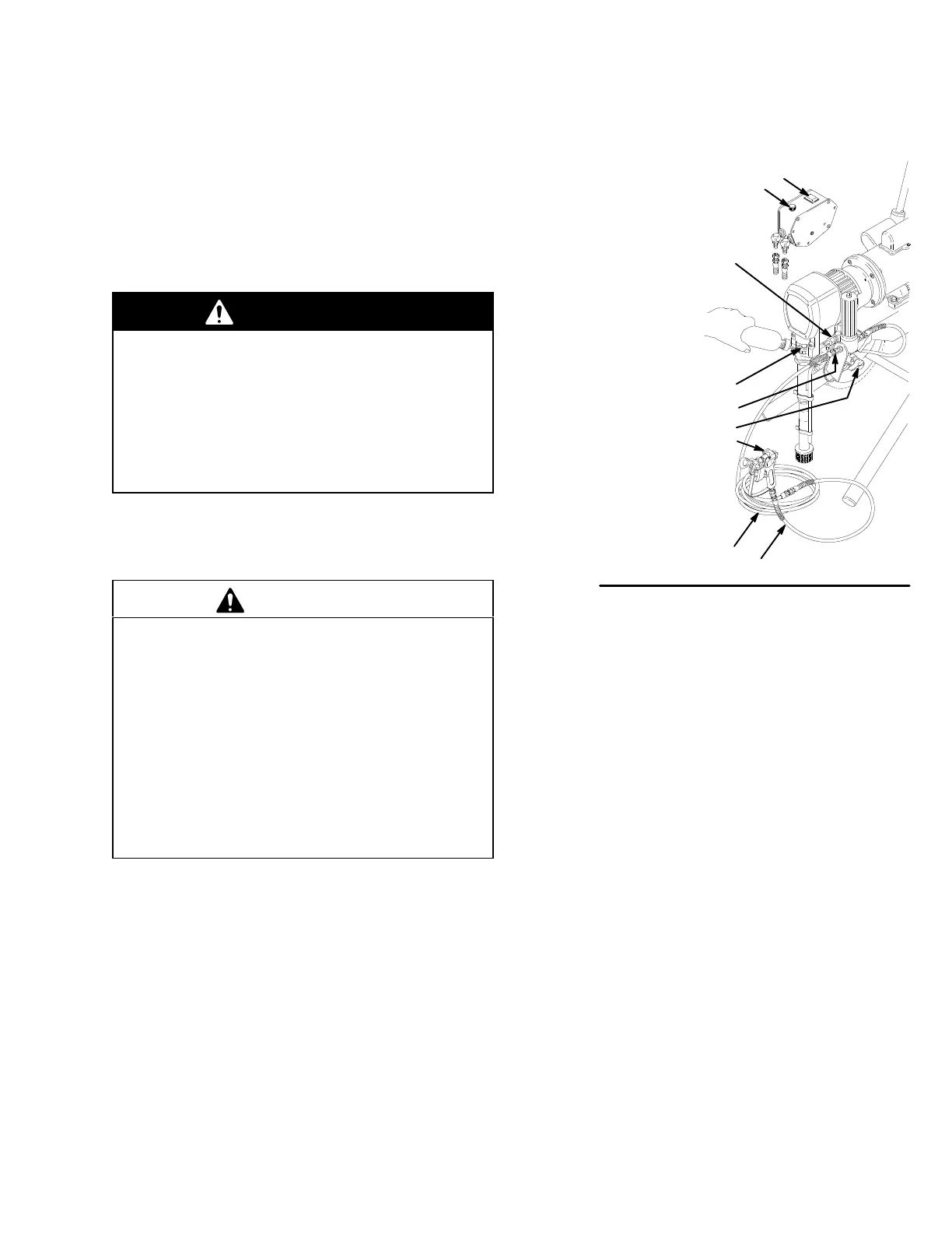
(Refer to Fig. 2)
a. Remove
the plastic cap plug from
the filter outlet
nipple
(E). Screw the 15.2 m main fluid hose (H)
onto
the nipple.
b. Connect the 0.9 m hose (J) between the fluid
hose
and the gun inlet.
c. DO
NOT use thread sealant on the hose and gun
connections.
DO NOT install the spray tip yet!
WARNING
If you supply your own hoses and spray gun, be
sure the hoses are electrically conductive, that the
gun has a tip guard, and that each part is rated for
at least
21.0 MPa, 210 bar) Maximum Working
Pressure.
These precautions reduce the risk of
serious injury caused by static sparking, fluid
injection, or over-pressurization and rupture of the
hose and gun.
2. Two
Gun Hookup
(Refer to
Fig. 2) Remove the cap
from
the secondary hose outlet (C). Attach an acces
-
sory
hose and gun to the 1/4 npsm(m) nipple.
CAUTION
T
o avoid damaging the pressure control, which may
result in poor equipment performance and compo
-
nent damage, follow these precautions.
1.
Always use nylon spray hose at least 15.2 m
long.
2.
Never use wire braid hose; it is too rigid to act as
a pulsation dampener
.
3.
Never install any shutof
f device between the filter
and the main hose. See Fig. 2.
4.
Always use the main filter outlet for one gun
operation. Never plug this outlet.
3. Fill Packing Nut/Wet–Cup (See Fig. 2) Fill the
packing nut/wet–cup (D) 1/3 full with Graco Throat
Seal
Liquid (TSL), supplied.
4.
Check the Electrical Service
a. Be sure the electrical service is 220/240 Volts,
50 HzAC, 10 Amp (minimum) slow blow. The
outlet
you use must be properly grounded.
b. Use a grounded extension cord which has 3
wires, each with a minimum 1.5 mm diameter,
and having a maximum length of 30 m. Longer
lengths or smaller diameter wires may affect
sprayer
performance.
5. Be sure your system is properly grounded be-
fore
operating it.
Read and follow the warning sec
-
tion,
FIRE AND EXPLOSION HAZARD
, on page 5.
KEY
A ON/OFF Switch
B
Pressure Adjusting Knob
C
Secondary Hose Outlet;
1/4 npsm(m)
D W
et–Cup;
Keep 1/3 full with TSL
E
Outlet Nipple;
1/4 npsm(m)
F Pressure Drain Valve
G Spray Gun
H
15.2 m Main Hose
J
0.9 m Hose
0481A
A
B
C
D
E
F
G
H
J
Fig.
2
6.
Plug in the Sprayer
.
a. Be
s
ur
e t
h
e O
N/OF
F s
witc
h (
A
) i
s O
FF
. S
e
e F
ig
. 2.
b. Plug
the power supply cord into a grounded elec
-
trical outlet that is at least 6 m away from the
spray
area to reduce the chance of
a spark ignit
-
ing
the spray vapors.
7. Flush
the pump
to remove the lightweight oil which
was
left in the pump to protect it from rust.
a. Before
using water–base paint,
flush with miner
-
al
spirits, followed by soapy water
,
and then flush
with
clean water
.
b. Before using oil–base paint, flush with mineral
spirits,
only
.
c.
Flush. See page 1
1.
8. Prepare the paint according to the manufacturer’s
recommendations.
a. Remove any skin that may have formed on top
of
the paint.
b.
Stir the paint to mix its pigments.
c. Strain the paint through a fine nylon mesh bag
(available
at most paint dealers) to remove par
-
ticles that could clog the filter or spray tip. This
is
probably the
most important step toward trou
-
ble–free
spraying.