Bearing
Housing & Connecting Rod
WARNING
To
reduce the risk of serious injury
, including fluid
injection or splashing in the eyes or on the skin, or
injury from moving parts, always follow the
Pres-
sure Relief Procedure W
arning
on page 6
before checking, adjusting, cleaning, or shutting of
the sprayer
.
Unplug the power supply cord!
NOTE:
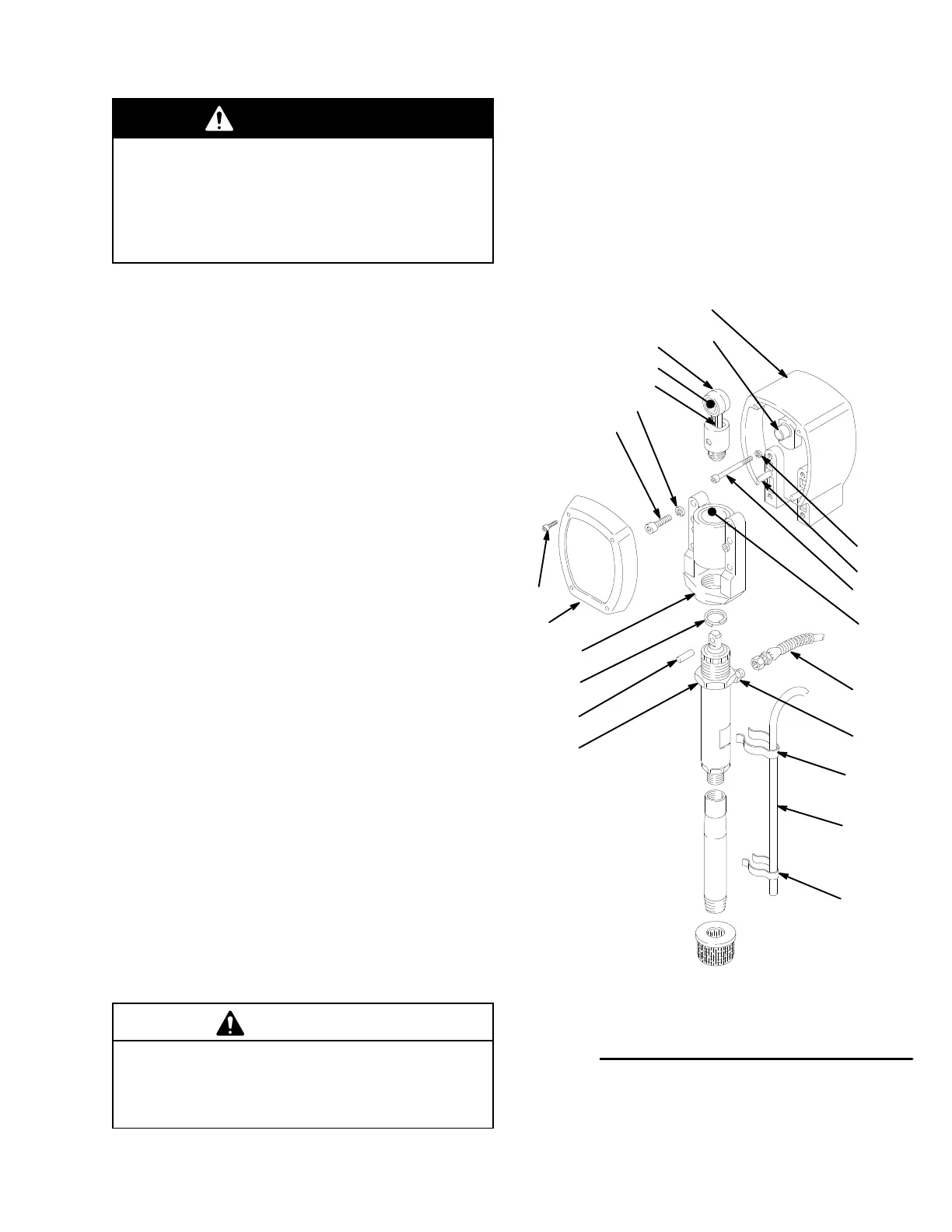
Refer to Fig 19 for this procedure.
Disassembly
1. Remove the front cover and screws (23,68). Re-
move
the spring clips (100,102) and the bypass hose
(101).
2. Disconnect the pump outlet hose (59) from the dis-
placement
pump outlet nipple (49).
3. Use
a screwdriver to push aside the retaining
spring
(26)
at the top of the pump. Push the pin (25) out the
rear.
4. Loosen the jam nut (27) with an adjustable wrench.
Unscrew
and remove the displacement pump.
5. Use
a
hex key wrench to remove the four screws (73)
and
lockwashers (74) from the bearing housing.
6. While
pulling the connecting rod (22) with one
hand,
lightly
tap the lower rear of the
bearing housing (21)
with
a plastic mallet to loosen it from the drive hous
-
ing
(20). Pull the bearing housing and the connecting
rod
assembly (22) of
f the drive housing.
Reassembly
1. Evenly
lubricate the inside of the bronze bearing
(C)
in
the bearing housing (21), and the inside of the con
-
necting
rod link (D),
with high–quality motor oil. Liber
-
ally
pack the roller bearing (E) in the connecting
rod
assembly
(22) with bearing grease.
2. Insert
the connecting rod
(22) into the bearing hous
-
ing (21).
3. Clean the mating surfaces of the bearing and drive
housings
(21 and 20).
4. Align
the connecting rod with the crank (A) and care
-
fully align the locating pins (F) in the drive housing
(20)
with the holes in the bearing housing (21). Push
the bearing housing onto the drive housing or tap it
into
place with a plastic mallet.
CAUTION
DO NOT use the bearing housing screw (73) to align
or seat the bearing housing with the drive housing.
These parts must be aligned using the locating pins
(F), to help avoid premature bearing wear
.
5. Install the screws (73) and lockwashers (74) on the
bearing
housing. T
ighten evenly to16–18 N.m.
procedure continued on page 20
20
73
TORQUE
T
O
(16–18 N.m)
23
74
26
59
49
25
E
D
A
F
C
68
11
24
22
21
27
100
101
102
Fig.
19