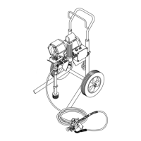
Clamp
NOTE: A standard steering wheel puller is required to
remove the clamp. Two 1/4–28 x 3 or 4 in. long
screws
are also needed.
NOTE:
Refer to Fig. 30.
1. Loosen
the two screws (16) on the clamp (3), work
-
ing
through the slot at the bottom of the clutch hous
-
ing (2).
2. Install two screws (B) of the tool (A) in two of the
threaded
holes in the clamp (3).
T
ighten the screws
(C) until the clamp comes of
f.
3. Skip ahead to Reassembly, page 29, Step 3., or
continue
to the right.
3
16
2
C
B
A
Fig. 30
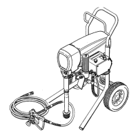
Clutch
Housing
NOTE: Refer
to Fig 31. The motor and clutch housing
were removed from the cart previously
.
1. Remove the four capscrews (62) and lockwashers
(9) which hold the clutch housing (2) to the adapter
plate (48).
2.
Remove the key (13).
3.
Pull of
f the clutch housing (2).
4.
Go to
Reassembly
,
page 29, Step 1..
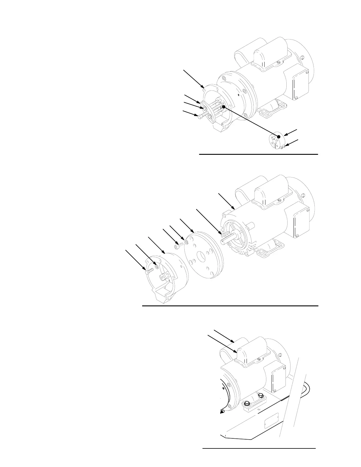
Motor
Capacitor and Inductor Coil
NOTE: A replacement capacitor may include a new re-
sistor,
installed. The start capacitor (1b) and the
inductor
coil (1c) are located under cover A.
The
run
capacitor (1d) is located under cover B.
NOTE:
Refer to Fig. 32.
1.
Remove the cover (A or B).
2. Remove the flag connectors from the old capacitor
or inductor coil.
3.
Connect flag connectors of the new component.
4.
Replace the cover
.
A
B
Fig. 32
47
74
2
9
62
13
48
1
Fig. 31