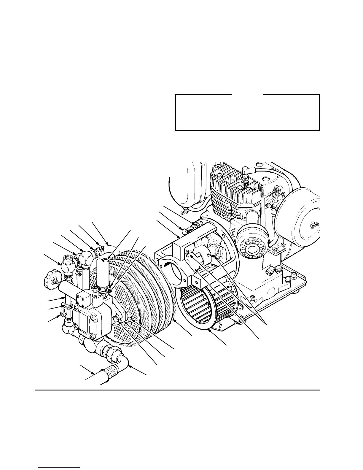
Replacing
the Hydraulic Pump
1. Follow
the
Pressure Relief Procedure W
arning
on
page
1
1.
Let the hydraulic system cool before begin
-
ning
the service procedure.
2. Unscrew the reservoir drain plug (51), having a
container
ready to catch the draining fluid.
3. Disconnect
the hose (7) from the bypass valve (9) by
loosening
the hose clamp (8). See Fig 12.
4. Loosen
the
hose clamp (8) and pull the hose (85) of
f
the
hose insert (5) near the elbow (3). See Fig 12.
5. Loosen the hose clamp (54) on the hose (53) just
above
the hydraulic pump (107). See Fig 12.
6. Loosen
the tube fitting nut (18) of hose (22). See Fig
12.
7.
Remove the two capscrews (150),
lockwashers
(66)
and washers (64) holding the pump (107) to the
support (1
17). See Fig 12.
8.
Pull the pump straight of
f the pump support.
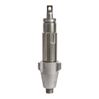
9. Loosen
the setscrews (108) on the pump half of
the
coupler
(109). See Fig 13.
10. Remove all fittings from the old pump and install
them
on the new pump in the same order
.
11. Check Dimension A as shown in Fig 13. When the
dimension is correct, tighten the setscrews (108),
slide
the new pump assembly onto the pump support
(117)
and recheck the dimension.
CAUTION
The correct coupling dimension is critical to avoid
improper coupler engagement to the coupler
spider
which will damage the coupler and make the
sprayer
inoperable.
12. Reconnect the hoses. Reinstall the reservoir plug
(51), and refill the reservoir with clean, Graco
approved
hydraulic oil.
Fig 12
114
108
109
49,66
107
150,66,64
115
18
22
9
8
7
4
152
3
5
8
85
53
54
52
113
112
117