307-615
14
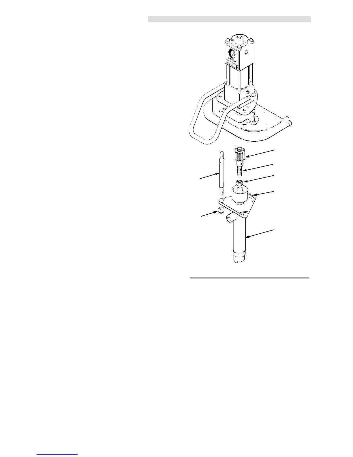
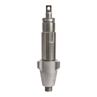
DISPLACEMENT PUMP SERVICE
Disconnect
the Displacement Pump
1. Flush the pump if possible. Stop the pump on the
down
stroke.
2. Follow
the
Pressure Relief Procedure W
arning
on
page
1
1.
3. Remove the suction tube and fluid hose from the
displacement
pump.
4. Unscrew
the three tie rod locknuts (48). See Fig
14.
5. Unscrew
the shouldered nut (35). Pull the displace
-
ment pump (46) of
f the tie rods (47).
6. Screw the jam nut (90) up onto the connecting rod
(91).
7. Remove the lower cotter pin (89) and unscrew the
connecting
rod (91) from the displacement rod (A).
8. Refer
to separate manual
307–862
for displacement
pump
repair instructions. Repair kit 206–735 is
avail
-
able.
Reconnecting
the Displacement Pump
1. Screw
the connecting rod (91) into the displacement
rod
(A) and replace the lower cotter pin (89). Screw
the jam nut (90) all the way down. See Fig 14.
2. Mount
the displacement pump (46) onto the tie rods
(47).
3. Screw the shouldered nut (35) onto the hydraulic
motor (29). Screw the tie rod locknuts (48) onto the
tie
rods (47) and torque to 35–50 ft-lb (47–68 N.m).
4.
Reattach the hoses to the displacement pump.
5. If the grounding wire was disconnected before
service,
be sure to reconnect it before operating the
sprayer.
6. Start
the pump and operate it slowly to check the tie
rods
for binding. Adjust the tie rod locknuts, if neces
-
sary
to eliminate binding.
Fig 14
47
48
35
91
90
89
46
TORQUE
T
O
35–50 ft-lb
(47–68 N.m)