9307-615
NOTE: In cold weather , run the engine for about 15
minutes with the bypass valve open before
starting the displacement pump, to help avoid
hydraulic
motor stalling.
i. Follow the Pressure Relief Procedure
Warning
on page 8, to shut of
f the sprayer
.
WARNING
To stop the engine in an emergency , depress
the engine STOP button. Close the bypass valve
if possible. See Fig 8. Then follow the Pressure
Relief
Procedure W
arning
on page 8.
If the motor stalls during operation, depress the
engine stop buttonturn OFF the ON/OFF switch. With
your
hand, firmly press straight down on the motor reset
button. Now try to restart the sprayer . If it will not start,
refer
to the separate motor manual, 307–158.
CAUTION
Never use a hammer to depress the reset button,
as
it could cause serious internal motor damage.
3.
Prime the Pump
a.
Be sure the gun safety latch is engaged.
b.
Don’t install the spray tip yet!
c. If the engine has not been started, follow the
procedure
in Step 2, page 8.
d.
Disengage the gun safety latch.
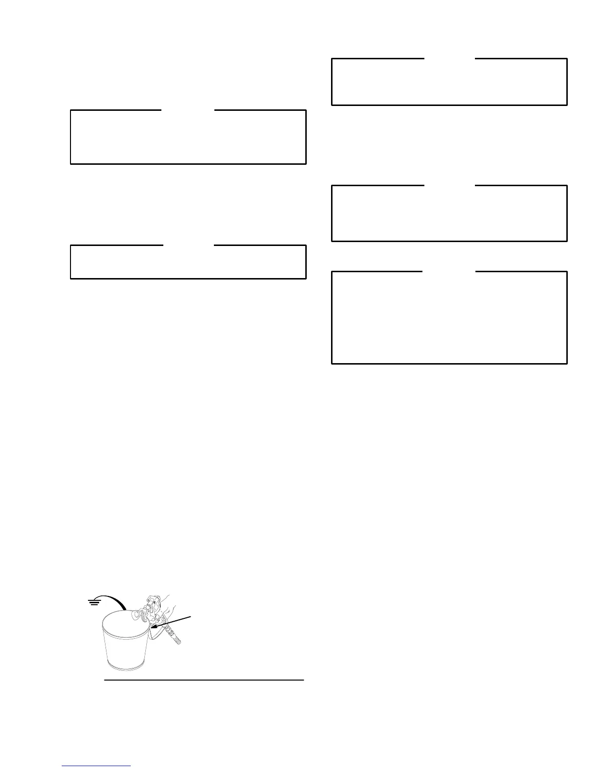
e. Point
the gun into a grounded metal pail and hold
a
metal part of the gun
firmly
against the pail. See
the
W
ARNING below
.
f. Squeeze
the trigger and
slowly
turn the pressure
control knob
clockwise
just enough to start the
pump.
See Fig 8.
g. Operate
the pump until all air is purged from the
pump and hoses and the fluid is flowing freely
from
the gun.
h. Release
the trigger and engage the safety
latch.
i. Turn the pressure control knob
counterclock-
wise
until all spring tension is relieved. Y ou will
be
able to feel it. The sprayer is now at the
lowest
pressure setting. T urning the knob further will
remove
it.
j. Follow
the
Pressure Relief Procedure
on page
8. Then install the spray tip in the gun as
instructed in the separate gun or tip instruction
manual. If you are using the RAC IV supplied
with
this sprayer
, see manual 307–848.
Fig 10
MAINTAIN
FIRM
METAL-TO-METAL
CONTACT
BETWEEN GUN
AND GROUNDED PAIL
4. Adjusting
the Pressure
a. Turn the pressure control knob
clockwise
to
increase and
counterclockwise
to decrease the
pressure. T
ighten the knob locknut to set.
b. Always use the lowest pressure that is neces-
sary
to completely atomize the fluid.
CAUTION
Operating the sprayer at a higher pressure than
necessary
wastes fluid, causes early
tip wear
, and
shortens
the sprayer life.
c. If more coverage is needed, use a larger tip
rather
than increasing the pressure.
d. Check
the
spray pattern. The tip size and angle
determines the pattern width and flow rate. See
the
separate manual received with your gun.
CAUTION
The engine throttle has been set and locked at
2800 RPM. The sprayer warranty will be voided
and
the hydraulic pump life shortened
if this adjust
-
ment
is changed.
5. Cleaning a Clogged Tip
WARNING
To
reduce the risk of a fluid injection injury
, NEVER
hold your hand, body or a rag in front of the spray
tip when cleaning or checking for a cleared tip. To
reduce the risk of a fire or explosion, always hold
the
gun firmly against the side of a grounded metal
waste
container when checking to see if the tip was
cleared
or when using a self–clearing tip.
a. Follow the Pressure Relief Procedure
Warning
on page 8.
b. Clean the front of the tip frequently during the
day to keep the fluid from building up and clog-
ging
the tip. T
o clean, and to clear a tip if it clogs,
refer
to your separate gun
instruction manual. If
you are using the RAC IV tip guard and
SwitchTip,
refer to manual 307–848.
6.
Shutting Off the Sprayer
a. Whenever you stop spraying, even for a short
break, follow the Pressure Relief Procedure
Warning
on page 8.
b. Clean the tip and gun as recommended in your
separate
gun or tip manual.
c. Flush
the sprayer at the end of each
work day if
using water–based fluid or if it could harden in
the
sprayer over night. See
FLUSHING
GUIDE
-
LINES, page 6. Use a compatible solvent to
flush, then fill the pump and hoses with solvent
such as mineral spirits to help prevent pump
corrosion.
Relieve pressure!
d. For long term shutdown or storage,
always
fill
the
sprayer with mineral spirits to prevent
pump
corrosion.
Relieve pressure!
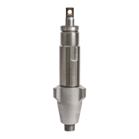
7. Adjusting the Intake V
alve Ball T
ravel.
a.
The pump is set to handle
medium volume, low
viscosity
fluid. T
o adjust
the pump for higher flow
or heavier viscosity fluid, disassemble the
intake
valve as instructed in manual 307–862 and
move the ball stop pin to a higher set of holes.
This
increases the ball travel.
 Loading...