Displacement
Pump
WARNING
To
reduce the risk of serious injury whenever you
are instructed to relieve pressure, always follow the
Pressure Relief Procedure
on page 7.
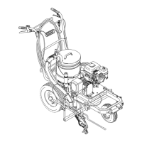
Removing the Pump See
Fig. 23.
1.
Flush the pump. Relieve pressure.
2. Hold the intake valve (223) with a wrench and un-
screw the suction tube swivel union (53). Unscrew
the
hose (133).
3.
Push the retaining spring (75) up. Push the pin (71)
out the rear
.
4.
Loosen the locknut (137). Unscrew the pump.
Fig. 23
76
75
71
137
133
223
204*
219
220
221*
202*
53
Disassembling the Pump
1. Unscrew
the
intake valve (223) and remove all parts.
See
Fig. 23.
2. Remove the plug (205). Unscrew the packing nut
(216).
See Fig. 24.
Fig. 24
*213
*209
216
205
*208
222
211
219
224
207*
0026
3. Tap
the piston rod (224) down and then pull it out the
bottom
of the cylinder (219). See Fig. 24.
4. Remove the glands (209*, 208*) and v–packings
(207*,
213*) from the throat. See Fig. 24.
5. Clamp
the flats of the piston rod (224) in a vise. Loos
-
en the piston (222). Unscrew the nut (211) from the
piston. Remove the glands (210*, 214*) and pack-
ings
(212*, 206*, 203*) from the piston. See Fig.
24.
Fig.
25
219
212*
213*
*210
205
*206
203*
*202
*208
*207
*209
218
216
*215
*214
224
137
*202
0027
Leather
Poly
Lips
must face down
Lips must face up
T
orque to
67 ft–lb (91 N.m)
 Loading...