39308-105
Reassembly
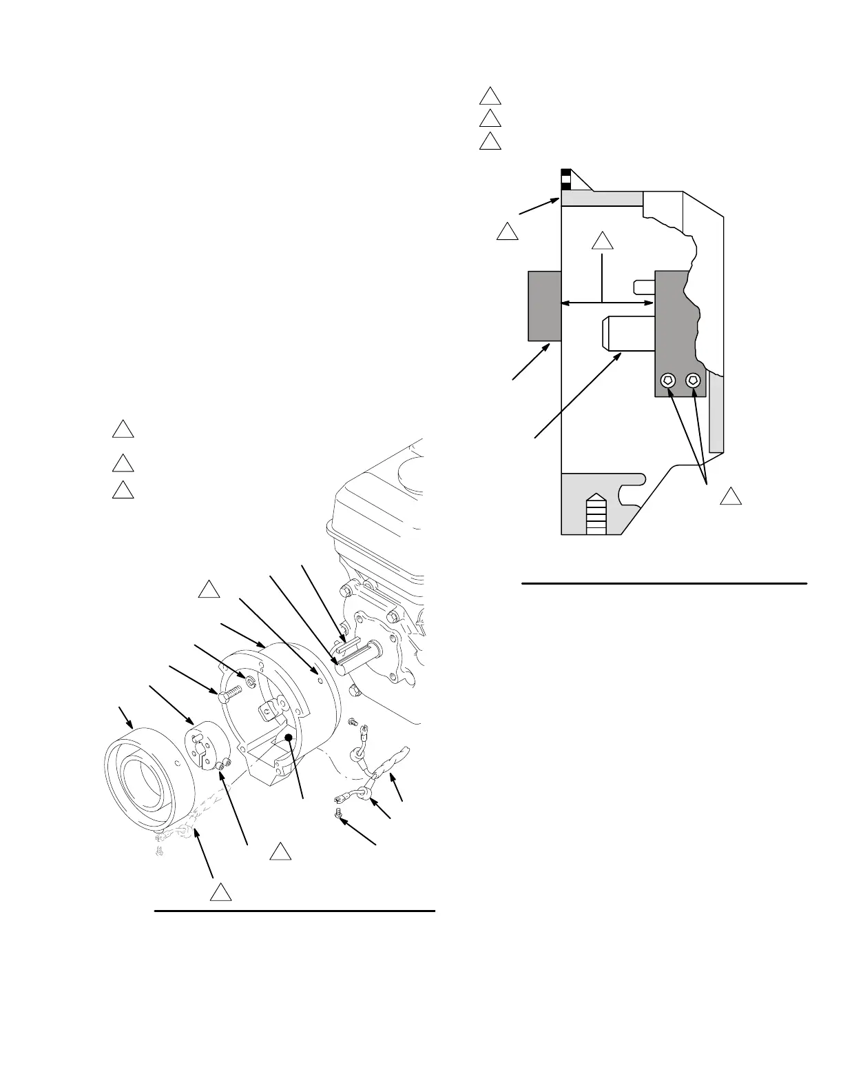
1. Install the clutch housing (61) , capscrews (156)
and
lockwashers (157) on the engine. See Fig. 47.
2.
Install the engine shaft
key (66).
See Fig. 47.
3. Install the clamp (68) onto the engine shaft (A).
Maintain
the 1.99 in.
+/– 0.01 (50.55 mm) dimension
shown
in Fig. 48.
To check the dimension, place a rigid, straight steel
bar (B) across the face of the clutch housing (61).
Use an accurate measuring device to measure the
distance between the inside of the bar and the face
of
the clamp. Adjust the clamp as necessary
.
T
orque
the
two screws (60) to 125 in–lb (14 N.m).
4. Connect
the wires of the harness (58) to the
screws
(57)
in both places on the field. Pull the plastic caps
(C) up and snap them over the screws. Guide the
wires
of
the harness (58) through the slot in the clutch
housing.
Slide the
field (70)
into the clutch. Align the
setscrew
chamfers in the field and the clutch housing
(61). T ighten the setscrews (62) oppositely and
evenly,
to 25 in–lb (2.8 N.m). See Fig. 47.
Fig. 47
Connect
wiring harness (58) here before
sliding field (70) into housing (61)
T
orque oppositely and evenly
to 25 in–lb (2.8 N.m)
57
58
70
68
156
157
61
66
60
A
T
orque to 125 in–lb (14 N.m)
62
C
D
0049
Fig.
48
1.99”
(50.55 mm)
60
SIDE CUTAWAY VIEW OF CLUTCH HOUSING
A
B
61
Face
of housing
0050
T
orque to 125 in–lb (14 N.m)
 Loading...