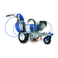
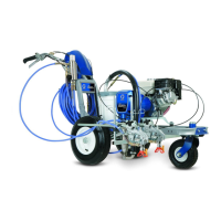
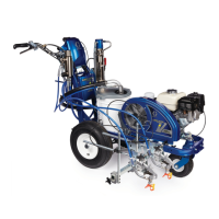
311021 15
Trigger Sensor Adjustment
Refer to Troubleshooting for trigger sensor adjust-
ment, and Operation Manual 311018.
Distance Sensor Adjustment
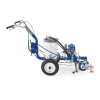
Gear Alignment
1. Relieve pressure; page 7.
2. Fig. 3. Remove dust cap (142) from wheel.
Remove nut (127).
3. Remove wheel (120) from LineLazer.
4. Align gear (67) with sensor .
a. Pull gear out from wheel with gear puller.
b. Push gear in toward wheel with mallet.
5. Install wheel (120) on LineLazer .
6. Install nut (127) until tight, then back off 1/4 turn.
Install dust cap (142) on wheel.
Sensor Height Adjustment
1. Remove wheel (120) from LineLazer.
2. Remove distance sensor (66).
3. Adjust sensor assembly height with two 17 mm
nuts of sensor so bottom surface of sensor is
0.638 +/--0.020 from bottom surface of shield.
Torque to 8 +/-- 2 in-lb.
Fig. 3
ti3680a
Inside of tire
.638 in.
Tire
Distance
Sensor
Gear
Frame
Axle
66
127
142
120
67
(120)
(66)
 Loading...