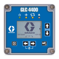
Controller Connections
Table 1 Key for Cable Connections, Electrical or Manual Air Controller
Ref.
Port Label Label
Color
Description
A
Mounting Holes for Power Supply
AUX-A Ports 1–3 Black
Auxiliary Ai
r Ports — Use 4 mm (5/32 in) tubing.
AUX-E Black
Auxiliary port for optional optocoupler wiring.
B Red
Bearing Air
— Use 8 mm (5/16 in) OD tube
BR Red
Bearing Air Return – Use 4 mm (5/32 in) tubing.
CAN
Black
Graco CAN/Power (24VDC)
DT White
Dump Val
ve Trigger – Use 4 mm (5/32 in) tubing.
MA Black Main Air Port — 1/2 in. npt
PT
Green Paint V
alve Trigger – Use 4 mm (5/32 in) tubing.
SI Gray Shaping Air Inner — Use 8 mm (5/16 in.) tubing.
SO
Blue
Shaping Air Outer — Use 8 mm (5/16 in.) tubing.
ST
Black
Solv
ent Trigger (Cup Wash) – Use 4 mm (5/32 in) tubing.
TA Brow
n
Turbine Air — Use 8 mm (5/16 in.) tubing with 1 mm (0.04 in) wall to
minimize pressure drop.
3A3954B 13