Controller Connections
Connect Air Li
nes
Graco Air Controllers are labeled with the same
reference letters as the applicator, for easier
matching.
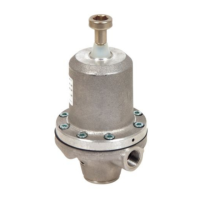
NOTICE
Use filtered air to prevent contamination of the
paint finish and to prevent damage to the air
bearing. Air that is not adequately filtered can clog
bearing air passages and cause bearing failure.
The ProBell Rotary Applicator Manual contains
detailed filtering specifications.
NOTE: For the turbine air (TA), bearing air (B),
shaping air inner (SI) and shaping air outer (SO)
lines, use 8 mm (5/16 in) OD tube with 1 mm (0.04
in) wall. For the bearing air return (BR) and the three
triggers (DT, PT, and ST), use 4 mm (5/32 in) tube.
NOTICE
Take great care to connect the air lines to the
correct ports. Incorrect air line connections will
damage the applicator.
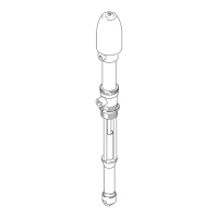
1. Connect all nine required air lines to the
applicator first. See your applicator manual for
instructions.
2. Air Activation Signal Lines (DT, PT, ST): Connect
the lines that provide air activation signals for the
dumpvalve(DT),thepaintvalve(PT)andthe
solvent valve (ST).
3. Shaping Air Lines (SI, SO): Connect the lines
that provide the shaping air inner (SI) and the
shaping air outer (SO).
4. Turbine Air (TA), Bearing Air (B), and Bearing Air
Return (BR):
• Electronic Air Controller: Connect these air line
to the Graco speed controller (if present) or to
another air control device in your system.
• Manual Air Controller: Connect these air lines
to the ports with the matching labels.
5. Connect the main air supply line into the main air
fitting (MA, Ref. 7) on the side of the box.
NOT
E: Once the air is applied, it will flow freely
out
Port B. The controller has no option to turn
th
is air off. (Manual Controller only)
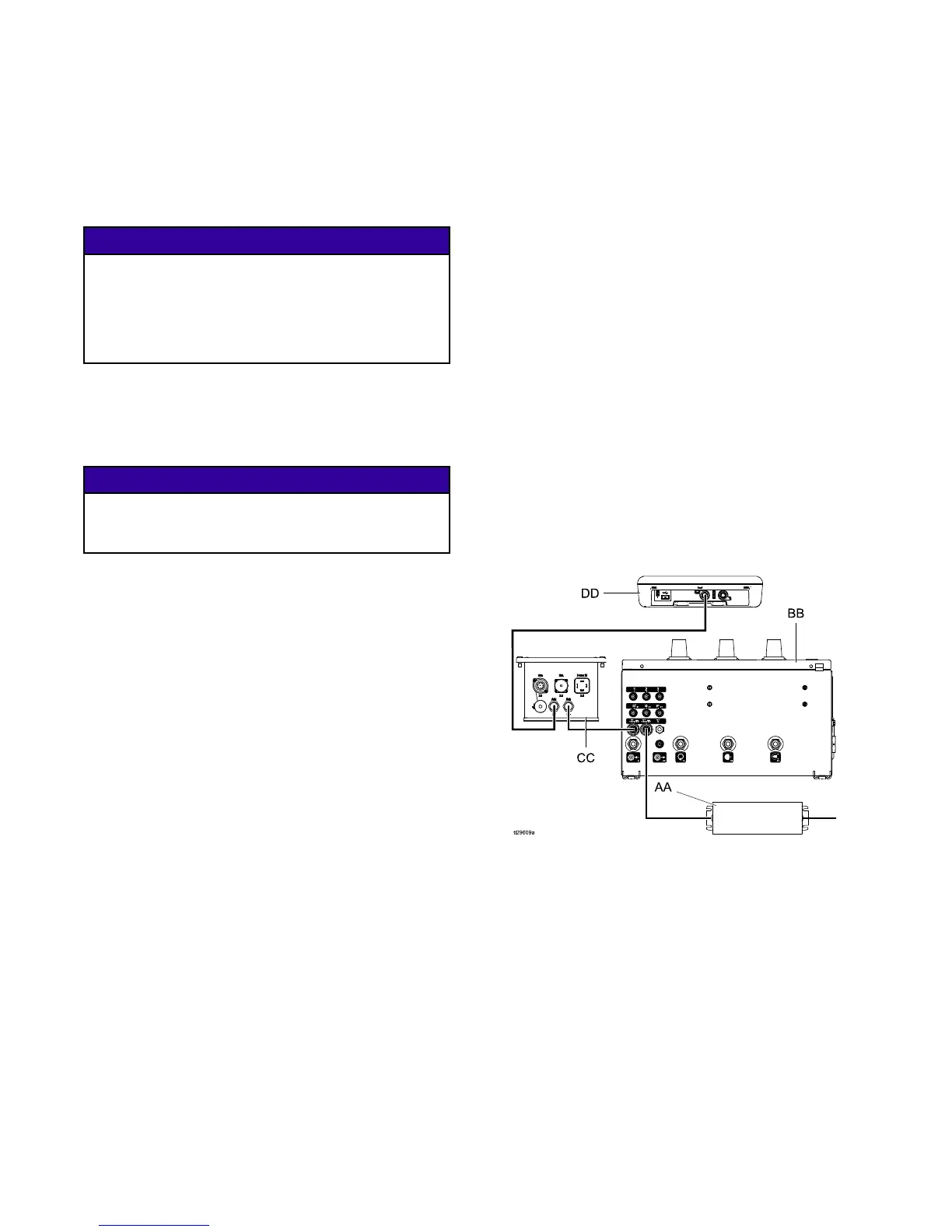
Connect Commu
nication Cables
The air controllers (Manual or Electronic)
communicate to the rest of the system over Graco
CAN cables. Each component and the power supply
must be on the Graco CAN network. The best
connection pattern depends on whether the Air
Controller is electronic or manual.
1. Connect a Gra
co CAN cable from Electrostatic
Controller
(CC) to the System Logic Controller
(DD).
2. If the power
supply is attached to the Air
Controller
, install the termination resistor (201)
on the spli
tter inside the box. NOTE: If the Air
Controlle
r was purchased as part of a system, the
terminati
on resistor will be installed at the factory.
If not, the
resistor comes with the power supply.
3. Manual Air
Controller:
a. Connect a Graco CAN cable from the power
supply (AA) to the right (inside) port on the
Air Controller (BB).
b. Connect a Graco CAN cable from the
other port on the Air Controller (BB) to the
Electrostatic Controller (CC).
4. Elec
tronic Air Controller (with Speed Controller):
a. Connect a Graco CAN cable from the power
supply (AA) to the lower/rear port on the
Speed Controller (EE)
b. Connect a Graco CAN cable from the Speed
Controller (EE) to the Air Controller (BB).
c. Connect a Graco CAN cable from the Air
Controller (BB) to the Electrostatic Controller
(CC).
1
4
3A3954B