Controller Connections
Connect Power
One power supply is required in the Graco CAN
network, typically mounted on the bottom of the
Speed Controller, or the Manual Air Controller.
1. Connect a pow
er cord to the power supply
connector. A
cord suitable for use in North
America is pr
ovided with the power supply. See
Technical Sp
ecifications, page 41. The power
supply is so
ld separately from the air controllers,
but include
d in system purchases.
2. Connect the
other end of the cord to AC power.
See Technic
al Specifications, page 41,formore
informati
on.
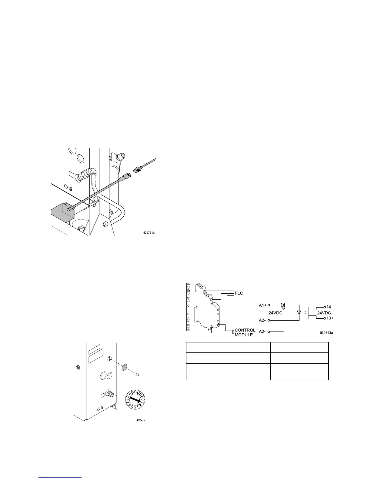
Set Air Control Identity
The air controller comes preset from the factory to
control one applicator. In two-applicator systems, the
identity of the control module must be set in order to
communicate with the system properly.
1. Remove plug (24) to access control module
rotary switch by pushing from the inside of the
box with a screwdriver.
2. Using a screwdriver, set the control module
rotary switch to “1” for the air controller that
controls the second applicator.
3. Replace the plug.
4. Restart the system by removing and reapplying
power.
Wiring the Pai
nt Trigger Input
The Paint Trigger Input provides a means to signal
the System Logic Controller to activate the paint
trigger solenoid. This normally open (maintained)
contact provides a signal to the system to indicate
whether or not to trigger spray device or spray device
is triggered (Input Only). If the input is OPEN the
system deactivates paint trigger solenoid. The input
must be maintained CLOSED to activate paint trigger
solenoid.
NOTE: The P
aint Trigger discrete input must be
enabled on
the System Logic Controller. If it is set
to ’Local’
or ‘Network’, the discrete input is ignored
and the spr
ay device trigger signal is handled via the
network c
ommunications, or manually. (see System
Logic Con
troller manual 3A3955).
The Paint Trigger Input uses an optocoupler to
protect the Graco ProBell air control box from outside
voltages.
• Optocoupler ports 13+ and 14 are wired to the
control module.
• Optocoupler ports A1+ and A2- are wired to the
external device or PLC.
Apply t
he 24 VDC signal to A1+ and GND to A2–.
Only on
e A2– port needs to be connected to GND, as
the two
ports labeled A2– are connected internally.
A1+ (relative to A2–)
Func
tion
24 V
DC
Paint Trigger Active
Less than 13.5 VDC
Paint Trigger
Inactive
16 3A3954B