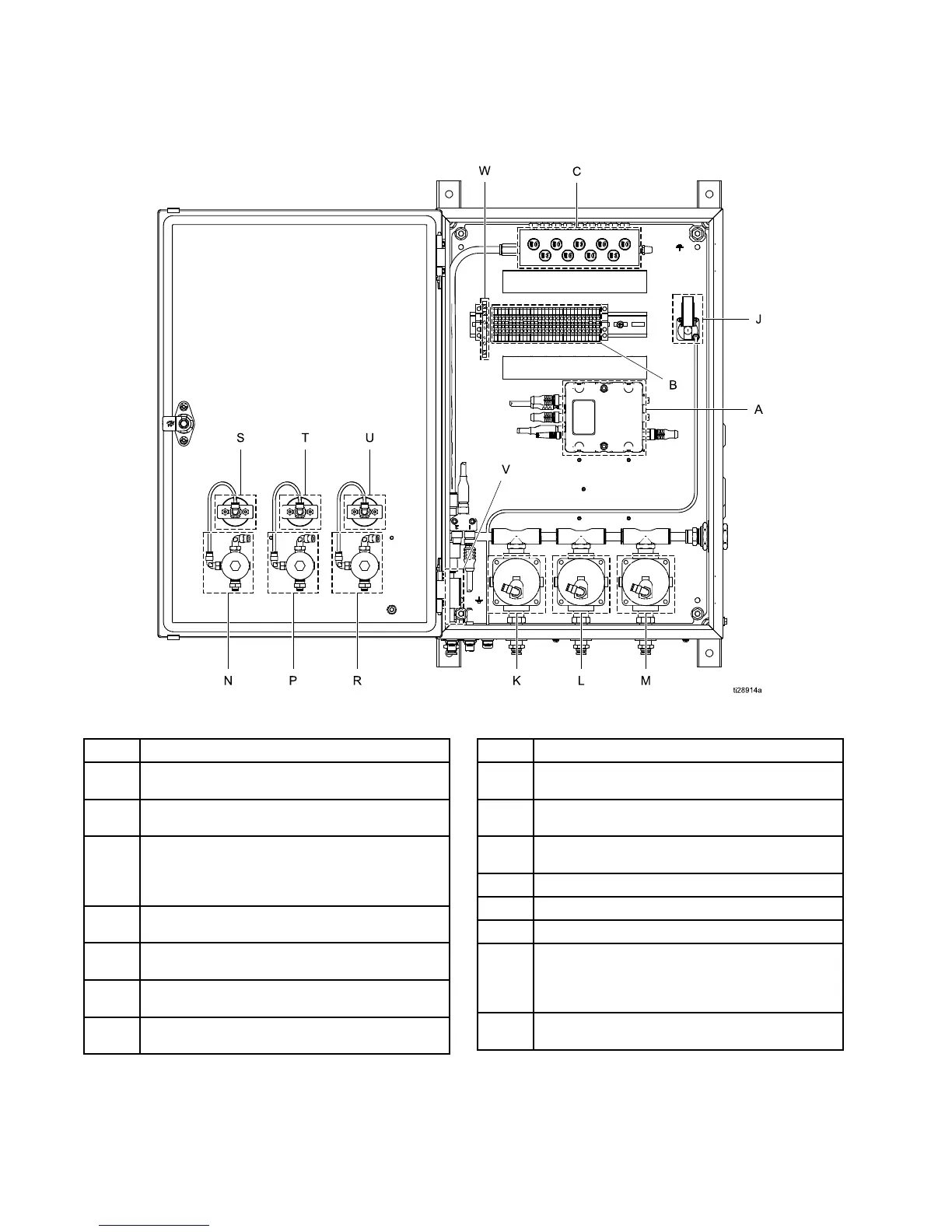
Component Ident
ification
Manual Air Con
troller
Ref. Component
A
Control Module — manages the operation
of all air controller components
B Terminal Blocks —provide electrical wire
connections
CSole
noid Valves — send air activation
sign
als for paint, dump, and solvent valves;
auxi
liary signals available for system
flexi
bility
J
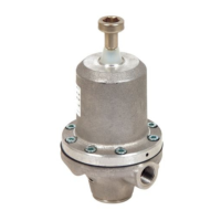
Pressure Switch — verifies that the bearing
air is at least 70 psi.
K
High-Flow Remote — piloted regulator for
turbine air
L
Hi
gh-Flow Remote — piloted regulator for
in
ner shaping air
M
High-Flow Remote — piloted regulator for
outer shaping air
Ref. Component
N
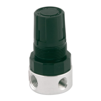
Outer Shaping Air Regulator — air pressure
signal to regulator M
P
Inner
Shaping Air Regulator — air pressure
signa
l to regulator L
RTurb
ine Air Regulator — air pressure signal
to re
gulator K
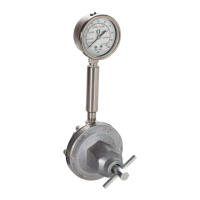
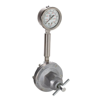
S Outer Shaping Air Gauge
T
Inner Shaping Air Gauge
U
Turbine Air Gauge
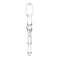
VAir
Filter — supplementary coalescing
air
filter, protects the bearing from any
par
ticles that get through the main air
filt
ering system.
W
Optocoupler — isolated input to trigger
paint valve from PLC
8 3A3954B