Service
10 3A5413F
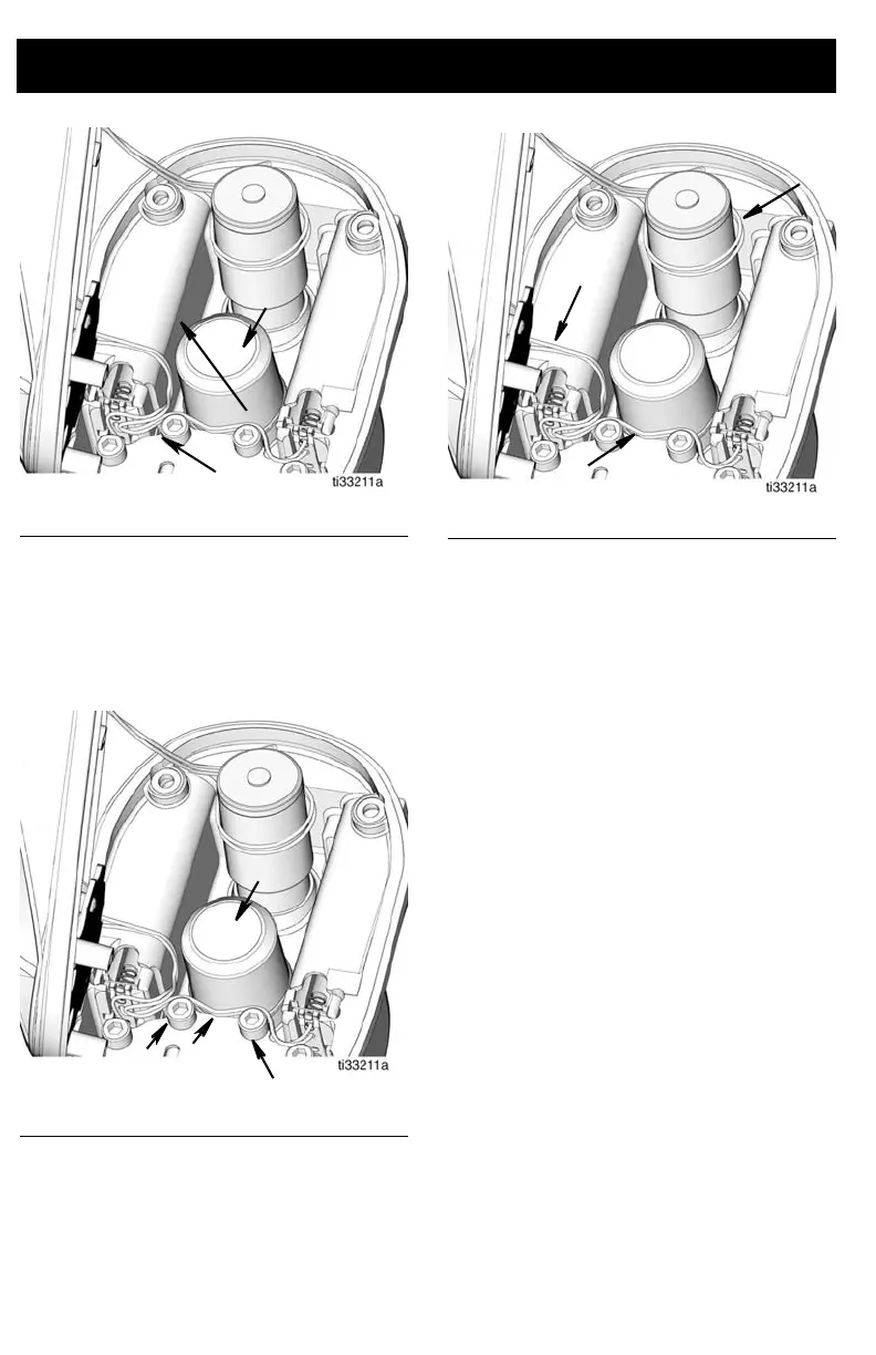
• Route black and white wire (f) between
the central valve boss (c) and gear cover
screws (e) (FIG. 8).
NOTE: This wire runs between the two
battery compartments.
F
IG. 9 shows the inside of the housing with all
wires routed correctly.
4. Take care that the wires will not be
pinched between the bezel (19) and
housing (12) and between the green
printed circuit board and the gear cover
when securing the bezel to the housing.
5. Verify o-ring (20) is in place on housing
(12). Install bezel (19) to housing using
o-rings (20) and 4 screws (21). Tighten
screws securely.
6. Install batteries and battery cover. See
Battery Replacement, page 7.
7. Recalibrate the metered dispense valve.
See Calibrate the Metered Dispense
Valve instructions provided in the
appropriate Metered Dispense Valve
Installation and Operation manual.
8. Pulse Pro meters must be registered and
configured per instructions found in
Pulse
TM
Metered Dispense Valve
manual.
SDP meters with Pulse FC enabled must
be configured per instructions found in
SDP8/SDP18 Preset Metered Dispense
Valve, Pulse FC Enabled manual.
FIG. 7
F
IG. 8
FIG. 9