Repair
7. Perform Pressure Relief Procedure, page 49.
8. Remove the system frame from the floor and
L-brackets.
9. Remove
two bolts and nuts and fold the electrical
enclos
ure backward.
10. Remove
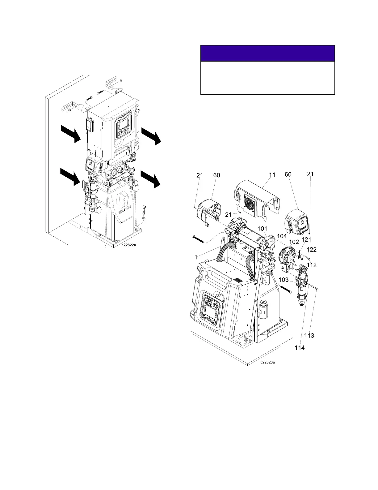
screws (21) and motor shroud (11).
Rest th
e motor shroud behind the motor without
strai
ning the fan power cable.
Note
Examine bearing housing (103) and
connecting rod (105). If these parts need
replacing, first remove the pump (106),
see Remove Pump, page 57.
11. Remove cover (60) and screws (21).
12. Remove cycle counter (121) from housing by
removing screw (122).
13. Disconnect pump inlet and outlet lines. Remove
screws (113), washers (115), and bearing
housing (103).
NOTICE
Do not drop gear cluster (104) when removing
drive housing (102). Gear cluster may stay
engaged in motor front end bell or drive
housing.
14. Remove screws (112, 119) and washers (114)
and pull drive housing (102) off motor (101).
Note
The A side dr
ive housing includes cycle
counter swi
tch (121). If replacing this
housing, re
move screws (122) and
switch. Rei
nstall screws and switch on
new drive h
ousing.
Figure 4
60 333024N