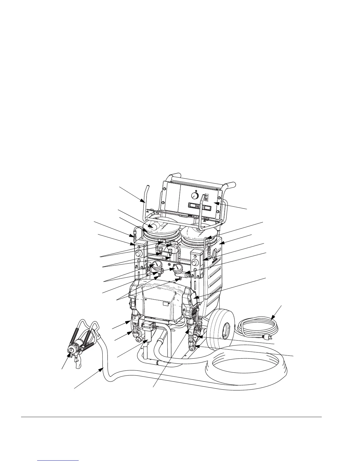
Component Identification
12 311075V
Component Identification
Key for FIG. 1
A Supply Tank A
B Supply Tank B
C Pump A
D Pump B
E Heater A
F Heater B
G Fluid Pressure Gauges
H Recirc/Spray and Overpressure Relief Valves
J Control Panel; see F
IG. 3, page 14
K Electric Motor and Drive Housings
L Insulated Hose Bundle
(includes circulation return hoses)
M Fusion Air Purge Spray Gun
N Desiccant Dryer (mounts on supply tank A)
P Recirculation Tubes
Q Air Line Inlet (quick-disconnect fitting)
R Outlet Hose Connections
S Return Hose Connections
T Fluid Temperature Sensors
U Hose Rack and Control Shield
V Fluid Inlet Ball Valves (1 on each side)
W Fluid Inlet Strainers (1 on each side)
X Power Cord
Y Air Filter/Moisture Separator
F
IG
. 1: Component Identification, Heated Packages (Part No. AP9572 Shown)
WLD
A
N
B
C
D
E
F
G
H
J
K
L
M
P
P
R
S
T
T
U
V
W
X
Q
Y