Repair
48 311075V
Control Board
Power Bootup Check
Control Board Replacement
2. Remove access cover (39) at back of con-
trol module to expose control board (406).
3. Disconnect all cables and connectors from
board. Remove two jumper wires (413)
from J10 pins 7-8 and 9-10.
4. Remove screws (408) and remove board
from control module.
5. Install new board in reverse order.
There is one red LED (D11) on the
board. Power must be on to check. See
F
IG
. 12 for location. Function is:
• Startup: 1 blink for 60 Hz, 2 blinks for
50 Hz.
• Motor running: LED on.
• Motor not running: LED off.
• Status code (motor not running):
LED blinks status code.
Check motor before replacing board.
See Electric Motor, page 53.
1. See Before Beginning Repair, page 41.
Relieve pressure, page 29.
Apply thermal compound between the
square steel piece on the back of the
board and the main aluminum plate.
Order Part No. 110009 Thermal Com-
pound.
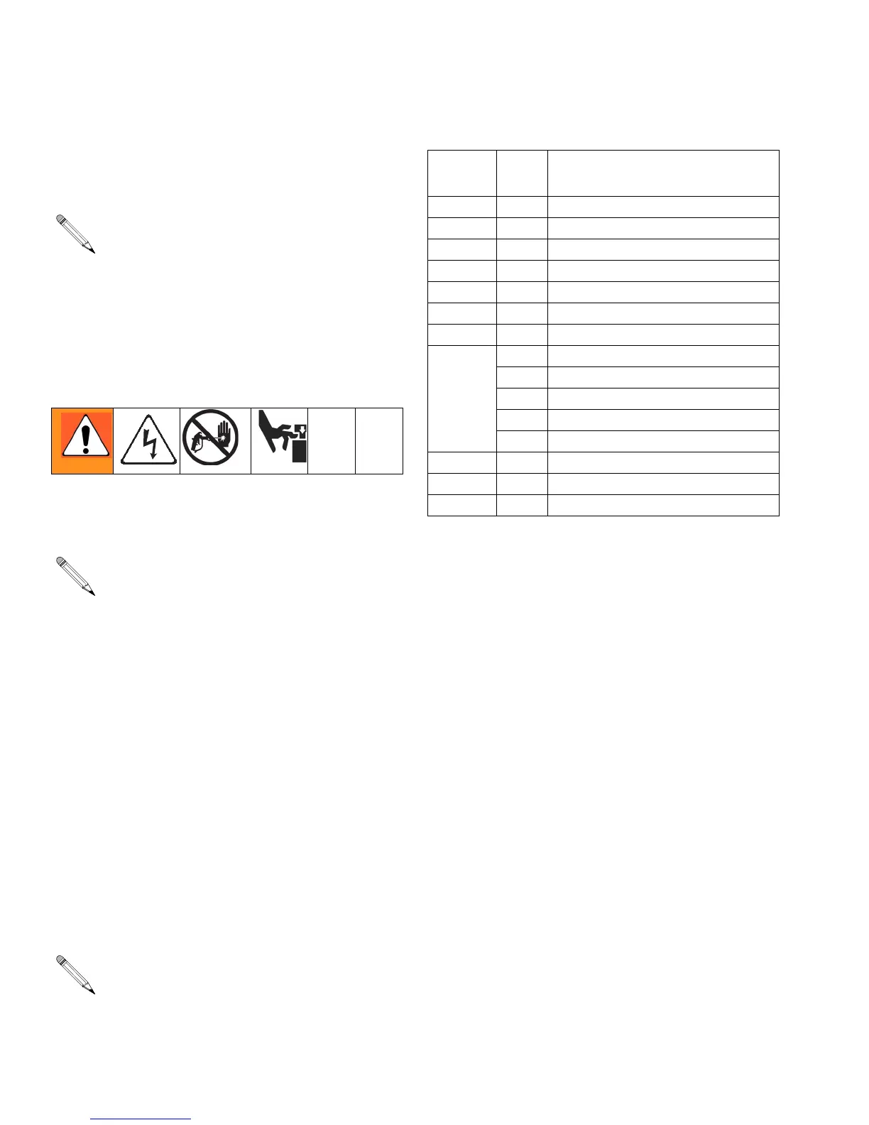
Table 6: Control Board Connectors
(see F
IG
. 12)
Board
Jack Pin Description
J1 n/a Main power from breaker
J2 n/a Function knob
J3 n/a Transducer A
J4 n/a Motor power (230 V units)
J7 1, 2 Motor thermal overload signal
J8 n/a Transducer B
J9 n/a Fan
J10 1, 2 Status indicator
3, 4 Not used
5, 6 Cycle switch signal
7-8 Jumpered
9-10 Jumpered
J11 n/a Motor power (120 V)
J14 n/a B temperature display
J15 n/a A temperature display