308–626
7
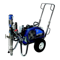
Installation
Electrical Grounding contrinued from page 6.
3.
Use only electrically conductive
fluid hoses
with a
maximum of 500 feet (150 m) combined hose
length to ensure grounding continuity
.
4.
Obtain electrical grounding continuity for the
spray
gun
by connecting it to a properly grounding fluid
hose and pump or sprayer
.
5.
Provide electrical grounding for these components
according to the local code: the
fluid supply
container
, the
object being sprayed,
and
all of
the solvent pails used when flushing.
Use only
metal pails, which are conductive. Do not place the
pail on a non-conductive surface, such as paper or
cardboard, which interrupts the grounding continu
-
ity.
6. To maintain grounding continuity when flush-
ing or relieving pressure
,
always hold a metal
part of the gun firmly to the side of a
grounded
metal pail, then trigger the gun.
Operation
Pressure Relief Procedure
INJECTION
HAZARD
T
o reduce the risk of serious injury
, in
-
cluding fluid injection, splashing in the
eyes or on skin, or injury from moving
parts, always follow this procedure whenever the
spray equipment is shut of
f, when checking or serv
-
icing any part of spray system, when installing,
cleaning or changing spray tips and whenever you
stop spraying.
WARNING
1.
Lock the gun safety knob.
2.
Shut of
f the power supply to the pump and open
any air bleed valves in the system.
3.
Unlock the gun safety knob.
4.
Hold a metal part of the gun firmly to the side of a
grounded
metal waste container
, and trigger the
gun to relieve pressure.
5.
Lock the gun safety knob.
6.
Open the pump drain valve to help relieve fluid
pressure in the pump, hose and gun. T
riggering
the gun to relieve pressure may not be suf
ficient.
Have a container ready to catch the drainage.
7.
Leave the drain valve open until you are ready to
spray again.
If you suspect that the spray tip or hose is completely
clogged or that pressure has not been fully relieved
after following the steps above, V
ER
Y SLOWL
Y
loosen the tip guard retaining nut or hose end coupling
and relieve pressure gradually
, then loosen completely
.
Now clear the tip or hose obstruction.
INJECTION HAZARD
The wallet-sized warning card provided
with this gun should be kept with the op
-
erator at all times. The card contains
important treatment information should a fluid injec
-
tion injury occur
. Additional cards are available at
no charge from Graco, Inc.
WARNING
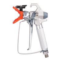
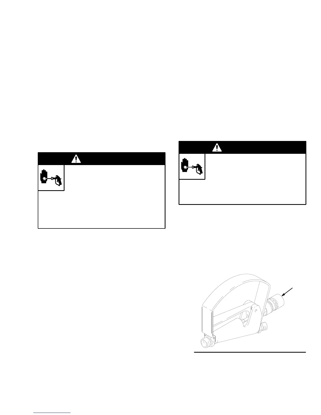
How to Use the Safety Knob
To
lock the safety knob (A), turn the knob fully clock
-
wise; this locks the needle in the forward position. T
o
unlock the safety knob, turn the knob fully counter
-
clockwise. See Fig. 2.
Fig. 2
A
04884