Repair
3A2989V 25
Pump Assembly (System
Module)
Prior to servicing the pump assembly you must first
remove either the entire pump assembly or the displace
ment pump and air motor individually.
Remove Pump Assembly
1. Follow Pressure Relief Procedure, page 7.
2. Close ball valve at metering pump inlet.
3. Disconnect fluid inlet line from the displacement
pump. Leave line connected to the tank.
4. Disconnect air motor.
a. Disconnect sensor cable, air line, and ground
wire from air motor.
b. Remove mounting screws (5) and washers (4)
holding air motor (2 or 3) to mounting bracket.
See F
IG. 7 on page 26.
5. Use lift ring on air motor to remove pump assembly.
6. Refer to Xtreme Displacement Pump manual
311762 to service or repair the displacement pump.
Refer to NXT Air Motor manual 311238 to service or
repair the air motor.
7. Reconnect ground wire and sensor cable. Follow
steps in reverse order to reinstall pump assembly.
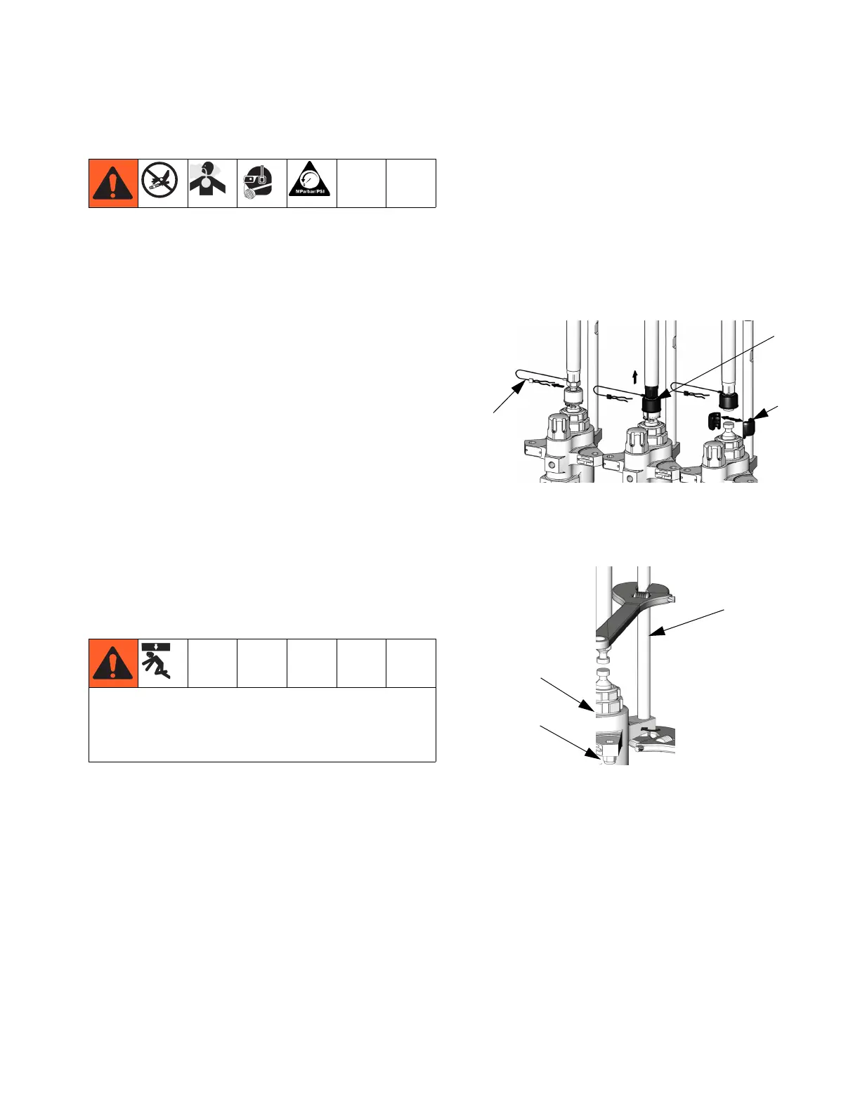
Remove Displacement Pump
Follow these instructions for removing only the displace
ment pump; the air motor will remain installed.
1. Follow Pressure Relief Procedure, page 7.
2. Close ball valve on tank outlet.
3. Disconnect fluid inlet line from the displacement
pump. Leave line connected to the tank.
4. Remove clip (2b), and slide coupling cover (2c) up
to remove coupling (2a).
5. Use a wrench to hold the tie rod flats to keep the
rods from turning. Unscrew the nuts (2e) from the tie
rods (2d) and carefully remove the displacement
pump (2f).
6. Refer to the Xtreme Displacement Pump manual
311762 to service or repair the displacement pump.
7. Follow steps in reverse order to reinstall displace
ment pump.
To avoid serious injury from falling objects caused by
the lift ring breaking, do not lift pump assembly by the
lift ring when the total weight of the pump assembly
exceeds 550 lb (250 kg).
 Loading...