Repair
24 3A2989V
Sensors
Replace Fluid Pressure Sensor
1. Close main air shutoff valve on air supply line and
on system.
2. Follow Pressure Relief Procedure, page 7.
3. Open control box cover. See User Interface/Con
trol Box, page 13.
4. Disconnect pressure sensor (831) from dosing
valve. See Ratio Control Valve Assemblies (28,
29) on page 74.
5. Disconnect other end of pressure sensor (831) from
FCM (507). See Control Box (16) on page 71.
6. Replace with new fluid pressure sensor, and recon
nect pressure sensor to FCM and dosing valve.
Hose Bundle Temperature Sensor (93)
1. Disconnect the M8 cable connection going into the
hose bundle.
2. Open up the hose bundle wrap and insulation until
sensor (93) can be removed easily without pulling
on cable.
3. Remove sensor (93).
4. Push new sensor fully into insulated portion of hose
bundle.
5. Close insulation and hose bundle wrap and re-tape.
Ensure there is no stress on the cable.
6. Reconnect M8 connector.
Replace Temperature (RTD) Sensors
This procedure applies to:
• Tank sensors mounted in the side of each tank near
the bottom (209). See parts illustration on page 56.
• Glycol heater for hose outlet manifold sensor (100).
See parts illustration on page 52.
1. Close main air shutoff valve on air supply line and
on system.
2. Follow Pressure Relief Procedure, page 7.
3. Disconnect the M8 cable connection.
4. Loosen the compression nut. Pull sensor straight
out of fitting (82 or 208).
5. Remove fitting (82 or 208).
NOTE: The compressed ferrule cannot be removed
from the sensor. A new compression fitting must be
used.
6. Apply thread sealant then replace compression
fitting (82 or 208). Tighten fitting in place.
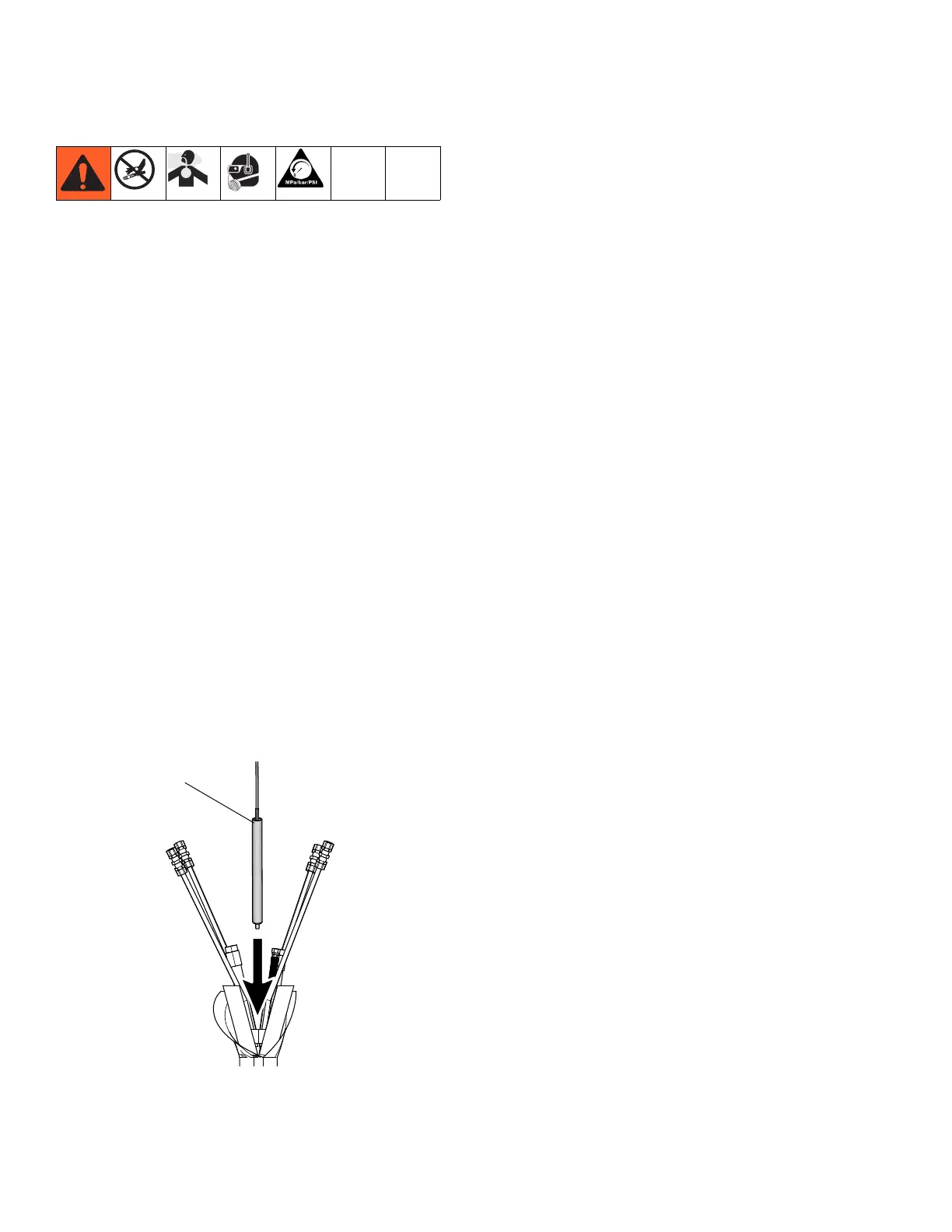
7. Position sensor (100 or 209):
• Tank: Insert sensor, leaving 5/8 in. (15.8 mm)
sheath outside fitting.
• Heater manifold: Insert sensor, leaving 1/8 in.
(3.2 mm) sheath outside fitting.
8. Install compression nut on sheath hand-tight then
tighten an additional 3/4 turn.
 Loading...