Repair
3A2989V 13
User Interface/Control Box
Remove Shroud and Front Panel of Control
Box
1. Close main air shutoff valve on air supply line and
on system. Depressurize air line.
2. Disconnect power.
3. Remove four nuts (21) and then remove front and
rear shrouds (19, 20).
4. Remove four nuts (17); leave two nuts on left side of
panel tight. Open front panel of control box (16).
See F
IG. 3.
Replace Single Solenoid Module
1. Remove Shroud and Front Panel of Control Box,
see page 13.
2. Disconnect solenoid cable connector (542) from the
solenoid (509a) being replaced. See Electrical
Schematics if necessary. For hazardous location
systems see Sensors Schematic Control Box on
page 43. For non-hazardous location systems see
Sensors Schematic Control Box on page 35.
3. Remove two screws (509b) from the solenoid being
replaced then remove solenoid (509a). See F
IG. 4.
4. Use screws (509b) to install new solenoid (509a).
5. Reconnect solenoid cable connectors (542).
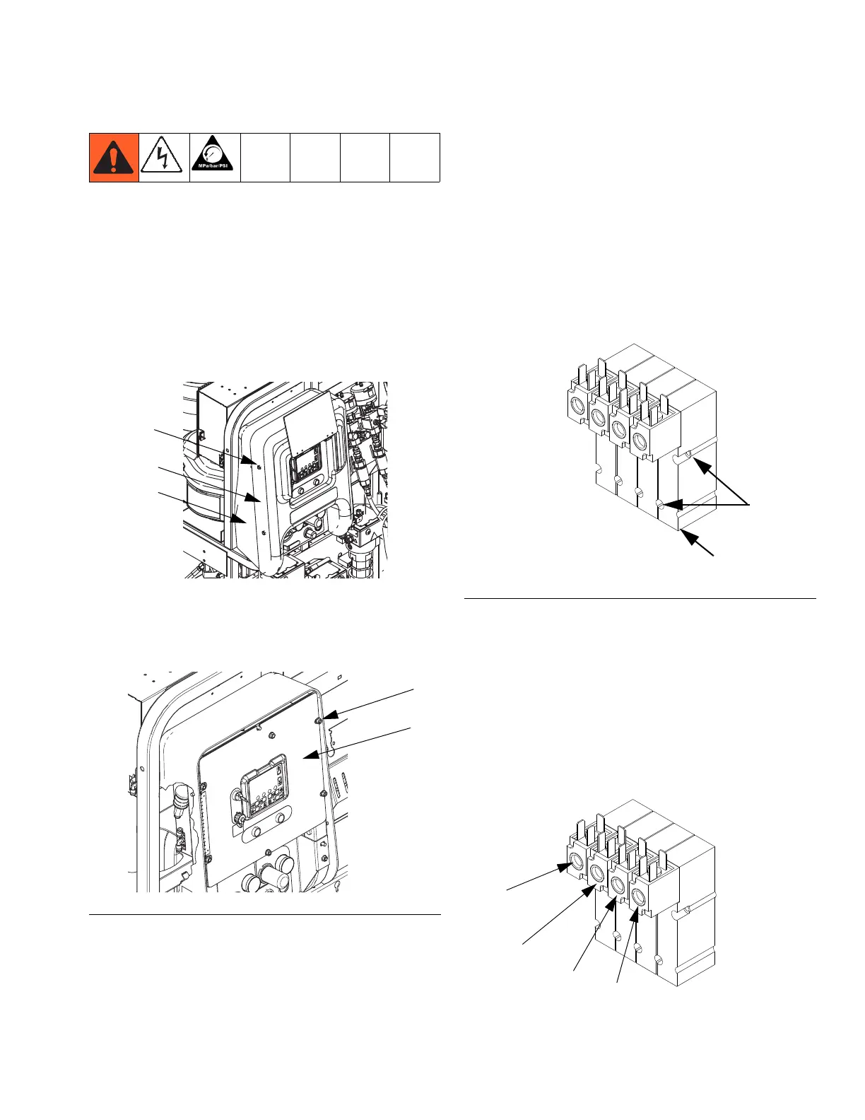
NOTE: From left to right, solenoid functions are as fol
lows:
• Dosing valve A (DVA) (normally open)
• Dosing valve B (DVB) (normally open)
• Pump A (PA) (normally closed)
• Pump B (PA) (normally closed)
F
IG. 3
FIG. 4
r_xm1a00_312359_313289_9_3
509b
509a
DVA
DVB
PA
PB
r_xm1a00_312359_313289_9_3
 Loading...