Repair
14 3A2989V
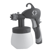
Replace USB Module
1. Remove Shroud and Front Panel of Control Box,
see page 13.
2. Disconnect CAN cables and USB cable from USB
module (519).
3. Remove two mounting screws from USB module
and remove module from base.
4. Follow steps in reverse order to install new USB
module.
5. Load software. See Replace USB Module.
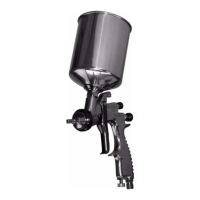
Replace Fluid Control Module (FCM)
NOTE: The USB module does not need to be removed
prior to replacing the FCM.
1. Remove Shroud and Front Panel of Control Box,
see page 13.
2. Remove all cables from FCM (518). Take note of
cable locations.
3. Loosen four mounting screws (535).
4. Slide FCM up and out of keyhole slots.
5. Follow steps in reverse order to install new FCM.
6. Load software. See Load software. See Replace
USB Module.
7. Most of the system configuration is stored in the
FCM. Use the display to change the configuration to
the values in the old FCM. See XM PFP operation
manual for instructions.
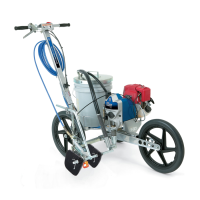
Replace Alarm
1. Remove Shroud and Front Panel of Control Box,
see page 13.
2. Disconnect alarm wires from alarm (517).
3. Unscrew alarm (517) and replace.
4. Screw in new alarm. Reconnect alarm wires.
5. Reinstall front panel of control box and reinstall
shrouds.
518
535
535
r_312359_313289_26
 Loading...