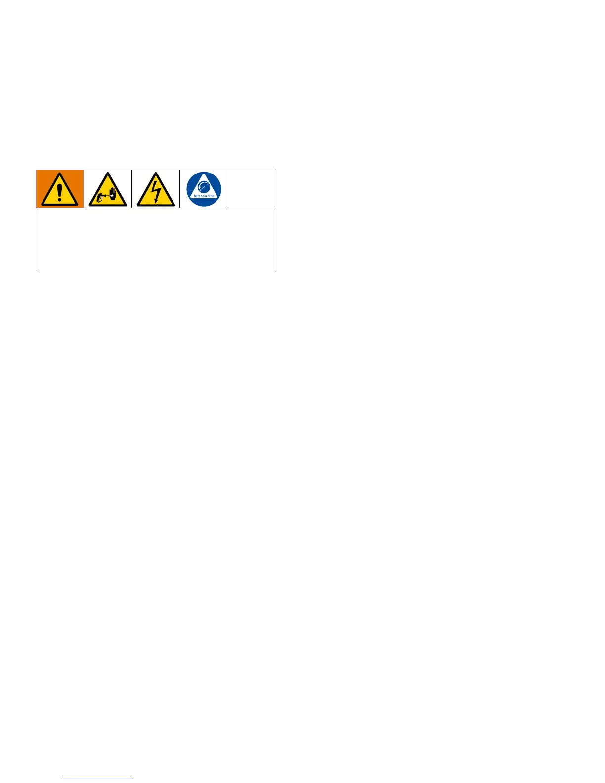
Installation
10 3A3320E
Installation
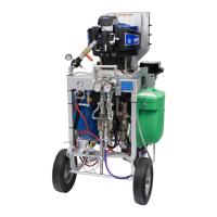
Installation for XP System with
NXT Motor
The procedures in this section are specific to each
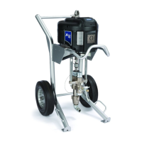
component of the XP PressureTrak. For sprayer
installation instructions, refer to the sprayer operation
manual.
1. Perform Pressure Relief Procedure. See your XP
Sprayer manual.
2. Remove the existing NXT air motor cover and front
(D) of the motor cover.
3. Remove the insert from the solenoid hole (F).
4. Install the solenoid (XE). Use the retainer (G) and
two bolts (H) to secure the solenoid.
NOTE: The holes in the casting may not have
threads, but the screws are thread-forming.
5. Pass the pressure sensor (4a and 4b) through slot
(K) and the solenoid (XE) through slot (J) in the
housing (XB) and secure the housing to the air
motor with two bolts (6).
6. Reinstall the front (D) and install the XP
PressureTrak cover (3).
7. Connect the pressure sensor cables to the
connectors on the circuit board.
NOTE: Be sure to match the color codes (connect
the blue cord to J6, circuit board labeled A and
green cord to J7, circuit board labeled B). Connect
the solenoid to J3, then connect the battery to the
battery terminals.
8. Slide the module (XA) into the channel of the
housing (XB) and secure with two screws (5).
9. Insert o-ring (11) on pressure sensor (XD).
Lubricate o-ring and install into the A side (blue) of
the manifold. Torque sensor nut to 40-50 in-lb
(54-67 N•m). Insert o-ring (11) on pressure sensor
(XD). Lubricate o-ring and install into the B side
(green) of the manifold. Torque sensor nut to 40-50
in-lb (54-67 N•m).
10. Install the pressure sensor harness (XD) through
clamp (10) and secure to the frame with screw (8)
and nut (9).
To reduce the risk of skin injection and shock, shut
down the XP Sprayer before installing your XP
PressureTrak. Follow the Shutdown and Pressure
Relief procedures in the XP Sprayer operation
manual.