NC
Common
NO
Common
Normally Open (NO)
Normally Open (NC)
NC
Common
NO
Common
NO
Common
+
NC
NO
NC
BioCompact II 610
BioCompact II 210, 310, 210/210, 310/210, 410
21
20
b i o l ine
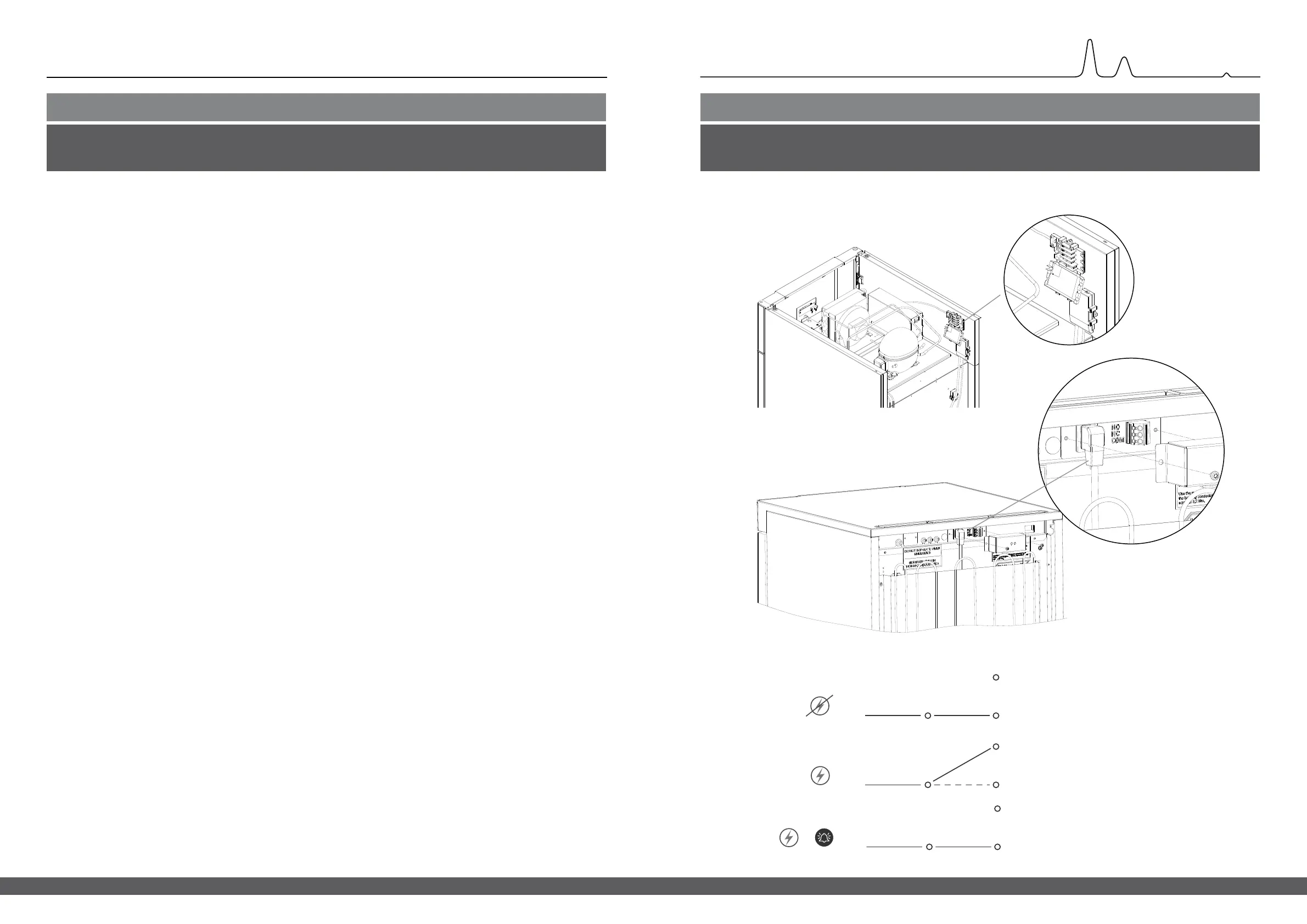
Voltage free contact
I-17*: The illustration shows the three connectors for the relay (used ex. in connecting to CTS or other external monitoring systems).
The three connections, are respectively. Common, NO and NC.
The moment when voltage is applied the controller draws the relay, this makes it possible for the controller to respond to both
high and low alarms, door alarms and power failures.
Temperature alarms and door alarms must be congured in the external alarm settings (EAL) before they will activate the
voltage free contact.
Find instructions on setting external alarms in the Parameter settings section.
Access to the voltage free contact is done according to the descriptions below:
BioCompact II 210, 310, 210/210, 310/210, 410
Unscrew the preload cover on the back of the cabient to access the voltage free contact block.
Two dierent sized strain reliefs are mounted into the preload cover for a secure tment of the wire for the voltage free contact.
Ensure that the preload cover is reinstalled after installing the voltage free contact.
The leaf spring in the preload cover must engage and preload the power supply plug.
Consult the section “Connection to power” for further information.
BioCompact II 610
The voltage free contact secured in place by the press-t plate that is pressed onto the block, thereby also preventing access to the
electrical circuit.
Connection of the voltage free contact should be done by a qualied installer.
Placement of voltage free contact
Normally closed circuit (NC)
*): Paragraph designation (I-1, I-2 etc) refers to the IQ (Installation Qualication)
 Loading...