2 3
b i o l ine
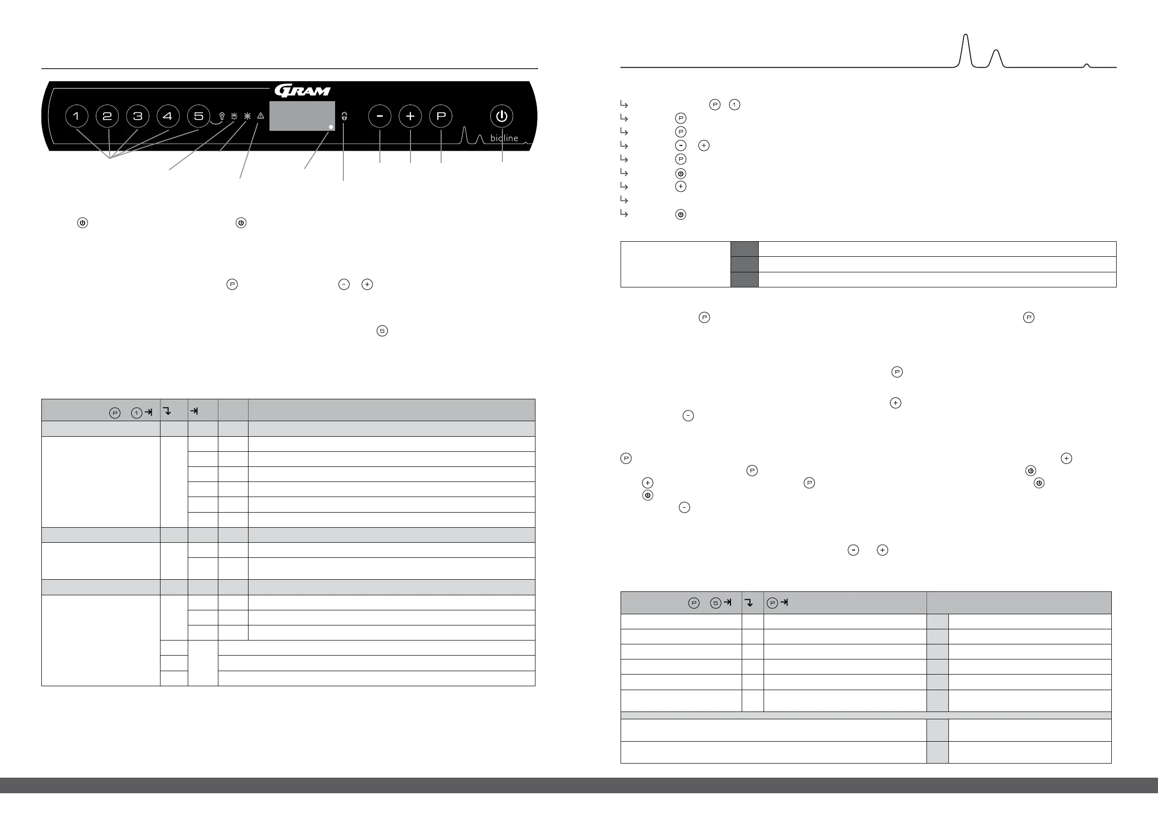
Quick guide – BioCompact II
Standby
Press the button to turn the cabinet on. Press the button for 6 seconds to turn the cabinet o. The software version of the
cabinet will be shown when turning the cabinet on, followed by the software variant. The cabinet is ready when the temperature is
displayed. The cabinet will automatically start a defrost-cycle when turned on, and terminate it again after a system check.
Setting the temperature
Temperature adjustments are done by holding the button and pressing either or
.
Conrm the settings by letting go of the buttons.
Lighting inside the cabinet – Only applicable to BioCompact ll cabinets with glass door
The settings for the lighting inside the cabinet can be changed by pressing and holding for 3 seconds.
There are two settings: 1) Light turns on when the door is open (o when closed)
2) Light is always on
Menu Access
+
Display code and its message
Local alarm settings LAL LHL [° C] Upper temperature limit. Code for activated alarm [A2]
LLL [° C] Lower temperature limit. Code for activated alarm [A3]
LHd [min.] Delay of upper temperature limit
LLd [min.] Delay of lower temperature limit
dA On/o Door alarm. Code for activated alarm [ A1]. [1=on/0=o]
dAd [min.] Delay of door alarm
bU On/o Acoustic signal for alarm codes [ A1], [ A2] and [ A3]. [1=on/0=o]
Oset of sensors CAL CA [K] Oset setting for A-sensor. Reference sensor for the refrigeration system
CE [K] Oset setting for E-sensor. Reference sensor for the display and alarms
CF [K]
Oset setting for F-sensor. Reference sensor for the low-temperature
protection
Low-temperature protection FP ACt On/o Activation/deactivation of low-temperature protection
tES On Test of low-temperature protection
SEt [° C] Setting of the cut-o temperature for the low-temperature protection
PrE […] Read-out of the real-time temperature of the F-sensor
ALL Activation of escorted alarm limits. [FAS]=locked limits/[ESC]=follows setpoint
dEF Number of defrosts per 24 hours (4 is factory setting)
dPS Reference sensor for the display (A, E or F)
User menu and alarm settings
Example: Setting the upper limits for the alarms; LHL
Press and hold + until the display shows LAL
Press to select LAL, LHL is now shown in the display
Press to select LHL, 25 is shown in the display
Press or to set the desired value for the upper temperature limit
Press to conrm the set value
Press to return to LHL
Press to reach the next level, LLL
LHd, LLd, dA, dAd and bU are located on the same level
Press three times to leave the user menu
Menu Access +
[° C]
Display code and its message
Sensor for refrigeration system P-A Value on sensor for refrigeration system F1 Error on sensor for refrigeration system
Sensor for evaporator P-b Value for evaporator sensor F2 Error on evaporator sensor
Sensor for condensor P-C Value for condensor sensor F3 Error on condensor sensor
Sensor 2 for condensor P-d Value for condensor sensor 2 F4 Error on condensor sensor 2
Sensor for display and alarms P-E Value for display and alarm sensor F5 Error on sensor for display and alarm
Sensor for low-temperature
protection
P-F
Value for low-temperature protection
sensor
F6
Error on sensor for low-temperature
protection
An overheated condensor can be caused by a clogged condensor –
clean the condensor
F7 Overheated condensor
Open door indicator. Alarm [A1] will activate if the door is open longer
than alarm limits.
-0- Door open
Acknowledging an acoustic alarm
Alarm code A1: Press to acknowledge. Temperature alarm codes A2 and/or A3: Flashes in the display. Press to acknowledge. The
display will continue to ash if the temperature is outside the alarm limits.
Latching alarms: A2, A3, A4, A5
Due to the potential implications of alarms, the red alarm triangle icon will turn on along with the corresponding alarm code will ash in
the display. The alarm state will remain on until acknowledged by pressing .
Reading Max/Min temperature
Read the higest recorded temperature inside the cabinet by holding down . Read the lowest recorded temperature inside the cabinet
by holding down
.
Reading the alarm history – Example [A2]
[A2] ashes in the display – This means that the temperature has exceeded the set value for the upper temperature limit, LHL. Press
to acknowledge the [A2]. The display continues to ash, indicating that there is information in the alarm history. Press , Htt (High
temperature time) is shown, press to see for how long the temperature was above the set alarm limit. Press to return to Htt.
Press to reach Ht (Highest temperature). Press to read the highest recorded temperature during Htt. Press to return to Ht and
press again to leave the alarm history function. The procedure for reading an [A3] alarm is identical, apart from entering the alarm
history with the button. When reading out temperatures below set limits, the parameters are Ltt and Lt. A ashing display with no
alarm codes indicates that the alarm codes have been acknowledged, but the alarm system contains information.
Resetting Max/Min and alarm history
Resetting of the Max/Min and alarm history is done by holding and for more than 3 seconds, an acoustic signal will be given when
reset is complete.
Alarms
Alarm codes
A1 Door alarm
A2 The upper alarm limits, (LHL) is or has been activated
A3 The lower alarm limits, (LLL) alarm is or has been activated
Sensor read-out and error codes
Temperature settings
Standby
Parameter settings
Defrosting
Key pad lock is
activated
N/A
Standby indicator
Alarms A2, A3, A4, A5
 Loading...