Section 3: Installation Information Page 11
Condensate outlet
Figure 3-4: Condensate outlet
3.5.4 Vibration
If the vibration from the heat pump is likely to cause a nuisance, use the
anti-vibration mounts (product code: HPIDFOOT/KIT) and fix the heat pump
securely to the mounts.
3.6 Installing the Heat Pump
3.6.1 Insulation
The complete water circuit, including all pipework, must be insulated to
prevent heat loss reducing the efficiency of the heat pump and also to prevent
damage due to frozen pipes.
3.6.2 Connecting the Heating System to the Heat Pump
• Water connections must be made in accordance with diagram in this
manual and the labels on the heat pump.
• Be careful not to deform the heat pump pipework by using excessive
force when connecting.
• Pipework should be flushed before connecting the heat pump.
• Hold the pipe end downwards when removing burrs.
• Cover the pipe end when inserting it through a wall so that no dust and
dirt enter.
• The heat pump is only to be used in a sealed heating system.
It must not be used as part of an open-vented system.
Before continuing the installation of the heat pump, check the following points:
• The maximum system water pressure is 3 bar.
• Make sure the hose is connected to the pressure relief valve to avoid any
water coming into contact with electrical parts.
• Air vents must be provided at all high points of the system. The vents
should be located at points which are easily accessible for servicing. An
automatic air purge valve is provided inside the heat pump. Check that
the air purge valve can operate.
• Take care that the components installed in the pipework can withstand
the water pressure.
3.6.3 System Connections
The system connections of the heat pump must be carried out using the flexible
hoses, valves and fittings supplied with the heat pump.
The hydraulic circuit must be completed following the recommendations
below:
1. It is important to install the isolation valves between the heat pump and
the building.
2. The system must have drain cocks in the lowest points.
3. Air vents must be included at the highest points of the system.
4. A system pressure gauge must be installed upstream of the heat pump.
5. All pipework must be adequately insulated and supported.
6. The presence of solid particles in the water can obstruct the heat
exchanger. Therefore, protect the heat exchanger using a magnetic filter
such as a Grant Mag-One, fitted internally.
7. After system assembly flush and clean the whole system, paying
particular attention to the state of the filter.
8. A new installation must be thoroughly flushed and cleaned before filling
and adding anti-freeze/biocide/inhibitor.
003 revO mm
Over 600 mm
Over 100 mm
Over 300 mm
Over 600 mm
HPID10
003 revO mm
Over 600 mm
Over 100 mm
Over 300 mm
Over 600 mm
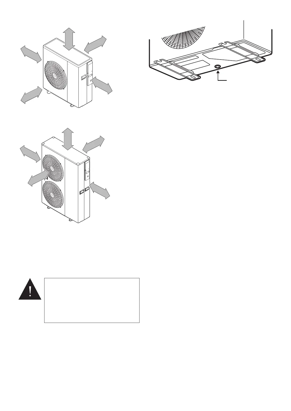
Figure 3-3: Clearances
3.5.3 Condense Disposal
The underside of the heat pump has a condensate outlet (refer to Figure 3-3)
that allows any condensate to drain from the heat pump.
Provision must be made to safely collect and dispose of the condensate.
For example, use 40 mm waste pipe to form a condensate disposal system
into which the condensate flows from the opening in the bottom of the heat
pump casing running to a suitable gulley or soakaway.
WARNING
It is essential that the condensate is able to
drain away and not allowed to run onto any
adjacent paths or driveways where, in winter,
this will result in icing and a potential hazard
for anyone walking near the heat pump.
The top of the concrete base must be either
level with, or above, the surrounding ground
level.
HPID10R32
HPID13R32 & HPID17R32
Figure 3-2: Clearances

 Loading...
