Section 7: Display PadPage 32
2. Fix the mounting plate to the wall.
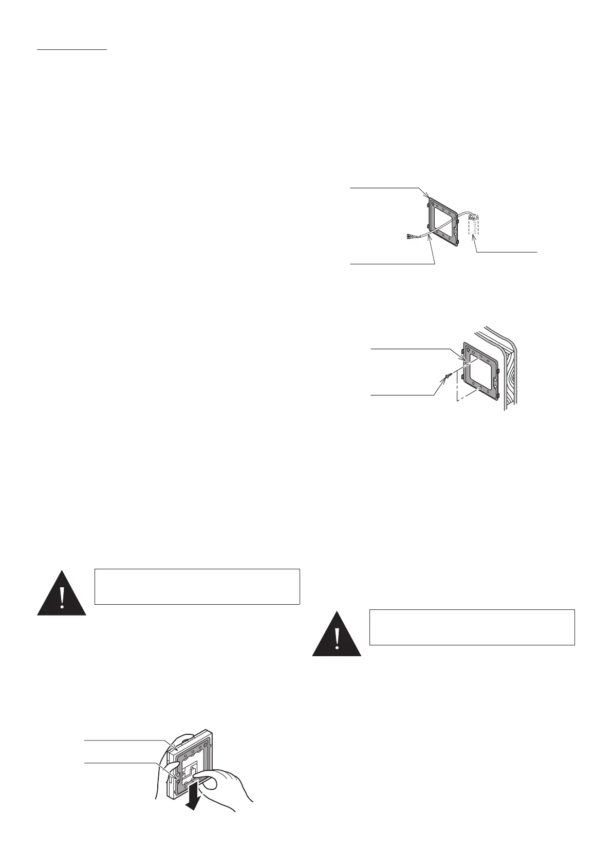
When the wiring is hidden
1. Before starting the display pad installation, pass the
wiring conduit through the inside of the wall (refer to Figure 7-2).
2. Pull out the display pad cable, passing it through the wiring conduit
and through the wiring hole in the mounting plate.
Figure 7-2: Wiring hidden
Wiring conduit
Remote controller
cord
When the wiring is exposed
1. Fix the mounting plate to a solid position on the wall with the two
screws provided (refer to Figure 7-3).
Screw
Mounting plate
Figure 7-3: Wiring exposed
• Do not over tighten the screws as this can deform or break the
screw hole of the mounting plate.
• Use the wall plugs if the mounting plate is to be fixed by screws to
tile, concrete or mortar.
• The display pad is connected using the two screw terminals on the
rear of the controller. Refer to Figure 7-5.
3. Connect the display pad cable to the terminal on the rear of the display
pad. Hook the wires under the clamp - locating it onto the four hooks
• The display pad has no polarity so wires can be connected either
way round.
4. Install the display pad.
Fix the display pad to the mounting plate by sliding it downwards.
5. After installing the display pad, check the fixing is secure.
If the mounting plate is not stable, tighten the screws further.
7.1 Display Pad
The display pad is used to:
• switch the heat pump on and off
• display room temperature
• display outdoor temperature
• display day/time (refer to Section 9.2 for setting the day and time)
• access and check/adjust display pad parameters.
• to access and check/adjust the heat pump control parameters (refer to
Section 9 and also Appendix A)
The display pad will also display any fault error codes should there be a fault
condition. Refer to Section 11.
It can also be used view the heat pump operating conditions at any point in
time using the Monitor Display function. Refer to Section 10.7.
7.2 Installation Requirements
Notes for the display pad installation
The display pad should be installed in a convenient position where the user
can easily access it to view the display and operate the on/off switch when
necessary.
It is a requirement of MCS installations that any fault indication (e.g. the fault
error codes displayed on the remote controller screen) should be visible to
the user.
• Do not install the display pad in damp conditions such as in the
bathroom. The display pad is not waterproof.
• Never install above a cooker or boiler or any other combustion device.
This would cause breakdown of electrical parts and deformation of the
outer case.
• Do not install in any location subject to steam.
• Do not install in any location subject to direct sunlight.
• Install the display pad a convenient position where it is out of the reach
of children.
• The display pad can be installed in the same room as underfloor
heating.
• Do not install in any location where industrial chemicals are used
(ammonia, sulphur, chlorine, ethylene compounds, acids, etc.).
• Route the display pad cable in such a way that is not in contact with
heat.
• Do not damage the display pad cable and use cable conduit to avoid
the damage.
•
7.3 Installing the display pad
• The connection between the heat pump and the display pad is low-
voltage, so it does not require electrical qualifications, but do follow
technical standards for electrical equipment in making this installation.
• Isolate the main power supply to the heat pump before connecting the
display pad cable.
1. Slide the mounting plate downward to remove from thedisplay pad
(refer to Figure 7-1).
Remote controller
Mounting plate
Figure 7-1: Removing the mounting plate
7 DISPLAY PAD
WARNING
The display pad must NOT be fitted inside the
heat pump casing.
WARNING
Do not use a power screwdriver. It can damage
the screw hole which can cause contact failure.

 Loading...
