Section 6: ElectricalPage 24
6.1 Main PCB
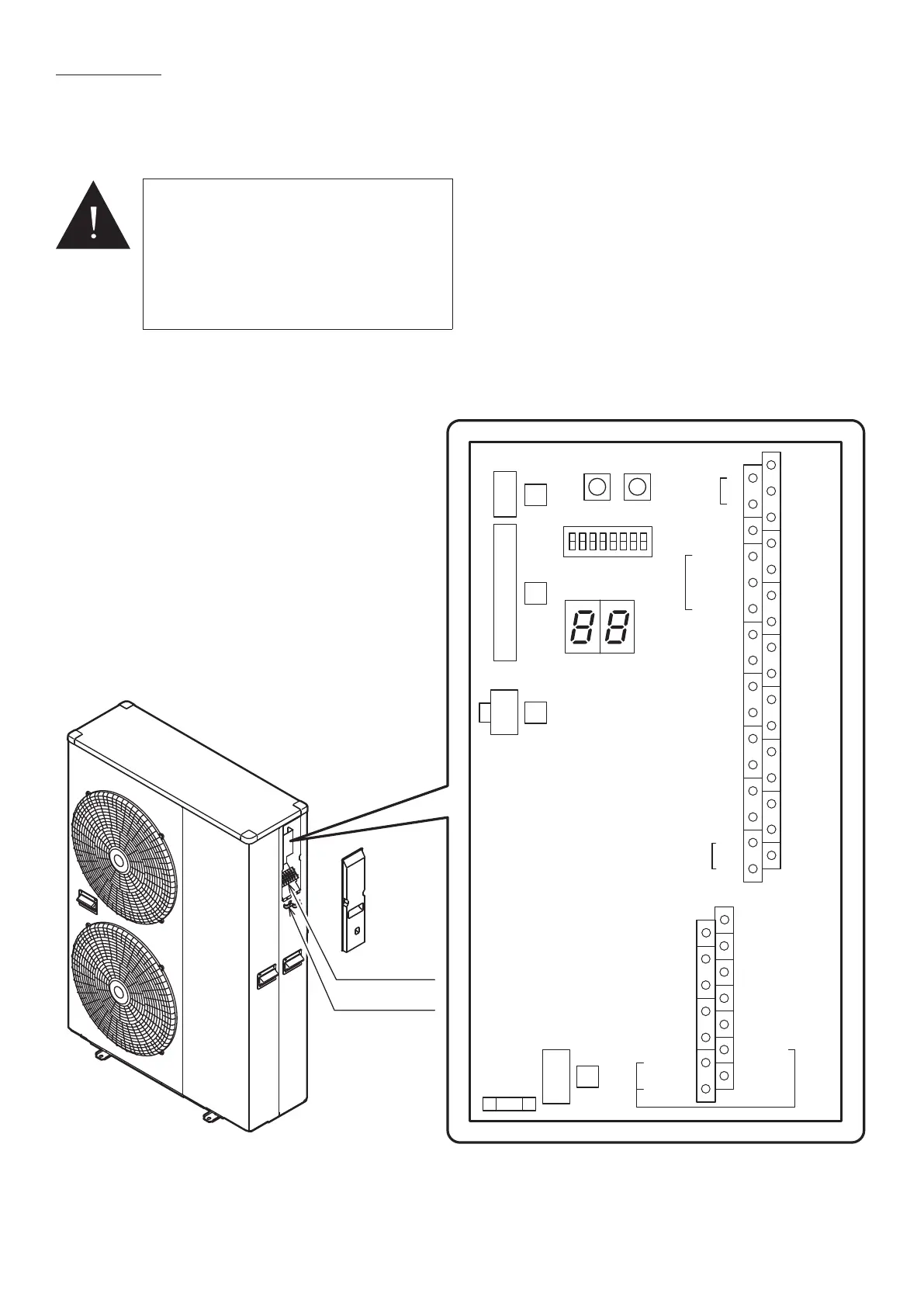
All wiring connections are made to the Terminal PCB (refer to Figure 6-1) and
terminal block (refer to Figure 6-3) inside the heat pump.
To access these connections, remove the wiring cover at the right hand end of
the heat pump.
Terminal block
Cable clamp
ON
Reset
SW.
Pump
SW.
OFF
Terminal
PCB
3
4
2
1
Remote
Controller
1
2
3
4
5
6
7
17
18
19
20
21
22
23
Humidity
Sensor
COM
DHW Remote
Contact
ON/OFF
or
EHS Alarm
GND
24VAC
COM
Control
DHW
T.probe
OUTDOOR
T.probe
BUFFER
T.probe
Mix water
T.probe
3-way
mixing
valve
RS485
+
-
Dehumidifier
Alarm
Pump1
Pump2
Neutral
N.C.
Neutral
EHS
Heating
Cooling
mode
output
Phase
Signal
3-way
valve
8
9
10
11
12
13
14
Dual Set
Point
Control
Heating
Cooling
mode
Flow
switch
Night
mode
Low
tariff
RS485
GND
45
46
47
48
49
50
31
32
24
25
26
27
28
29
30
15
16
N
41
42
43
44
51
52
Electric
heater
Figure 6-1: Terminal PCB
6 ELECTRICAL
WARNING
Electric shock may cause serious personal injury
or death.
All electrical work must be undertaken by
a competent person. Failure to observe this
legislation could result in an unsafe installation
and will invalidate all guarantees.
All electrical connections made on-site are solely
the responsibility of the installer.

 Loading...
