Section 6: Electrical
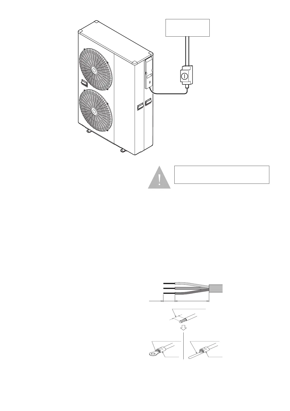
Strip ends of connecting cables in accordance with Figure 6-6.
Crimp terminals with insulating sleeves can be used if required as illustrated
in the diagram below for connecting the wires to the terminal block. Stranded
conductors shall not be soldered.
• Use a circuit breaker with a 3 mm clearance of air gap between the
contacts.
• Be sure to FULLY insert the cable cores into the proper position of the
terminal block.
• Faulty wiring may cause not only abnormal operation but also damage
to PCB board.
• Fasten each terminal screw securely.
• To check the connections are secure, pull the cable slightly.
10 mm 30 mm
Terminal block
Crimp terminal
Stripped wire :10mm
Sleeve
Crimp terminal
Sleeve
PCB(Terminal)
Figure 6-5: Stripping the cables
Lockable
isolator
Consumer
unit
Figure 6-4: Heat pump, isolator and consumer unit
6.4 Wiring first fix options
Mains supply
All heat pump models to have a twin and earth from main fuse board wired to
outdoor unit through an external isolator
6kW – 3 x 2.5mm2 – 16A RCBO
10kW – 3 x 4mm2 – 20A RCBO
13/17kW – 3 x 6mm2 – 32A RCBO
Grant wiring centre – located in cylinder area
5 x 0.75mmsq from Grant wiring center to the heat pump externally, sheilded
if over 30m.
Heat pump controller
2 x 1mm2 shielded cable from the Grant wiring centerto the controller and
should be shielded.
Immersion
3 x 2.5mm2 from main fuse board to immersion wired through Grant supplied
time boost kit
Cylinder Stat
Live & Neutral – linked from L&N on Grant wiring centre – 2 x 1.5mm2
Load & Common – 2 x 1mm2 from wiring centre to cylinder stat.
Note: If using pre plumbed cylinder, the cylinder wiring is already done.
If underfloor heating is present
Boiler/heating call cable from underfloor heating wiring centre/s to Grant
wiring centre – 2 x 1mm2
UFH circulating pump/valve wired back to Grant wiring centre – 2 x 1mm2
Page 26
In the case of long cable runs, selection of
correct cable must be done in accordance with
BS 7671 (IET Wiring Regulations)
NOTE

 Loading...
