Section X: TBC Page 29
ISOLATOR
HEATMISER UH8
CONTROLLER
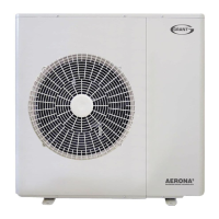
HEAT PUMP
MOTORISED
VALVES
IMMERSION BOOST KIT
CYLINDER THERMOSTAT
GRANT WIRING CENTRE
(Must be within 1 metre of the
heatpump, but not fitted on the
unit casing)
CORE CSA mm²
Main Supply Grant AERONA³ 6kW HP1D6R32 (11.2A) 3 2.5*
Main Supply Grant AERONA³ 10kW HP1D10R32 (17.5A) 3 4.0*
Main Supply Grant AERONA³ 13kW HP1D13R32 (23.0A) 3 6.0*
Main Supply Grant AERONA³ 17kW HP1D17R32 (25.3A) 3 6.0*
2 Signal cable Heat Pump - Remote 5 0.75
3 Fuse Board to Immersion kit 3 2.5
4 Fuse board to Grant Wiring Centre 3 0.75
5 Grant Wiring Centre to Circulating pump 3 0.75
6 Grant Wiring Centre to Heatmiser UH8 3 0.75
7 Heatmiser UHF to Room Stats 4 0.75
No. DESCRIPTION
CABLE
1
* Indicative only -Final cable sizing to be deterined by the installer
1
2
3
4
5
6
7
GRANT HEAT PUMP
CONTROLLER
IMMERSION
FUSED
ISOLATOR
FUSED
ISOLATOR
CIRCULATION PUMP
(OPTIONAL)
The system diagram is only a
concept drawing, not a detailed
engineering drawing,and is not
intended to describe complete
systems, nor any particular system.
It is the responsibility of the
system designer, not Grant IRL, to
determine the necessary
components for and configuration
of the particular system being
designed including any
additional equipment and safety
devices to ensure compliance with
building and safety
code requirements.
Section 6: Electrical Page 29
6.10 Wiring first fix options

 Loading...