212
Detail program description - Control adjust
model may become uncontrollable and "tear" across the
fl ight fi eld completely out of control, putting the pilot and
spectators at risk.
Therefore, it would obviously be benefi cial to program
the the function "Motor off" at the very least, in order to
prevent such risks. If necessary, seek the advice of an
experienced pilot in order to fi ne a "logical" setting for
your model.
And then another brief notice regarding the three
possible versions of the mx-20 HoTT transmitter for
the setting of Fail Safe:
The easiest, and recommended, way to fail-safe settings
is the use of the "Fail Safe" menu, which can be
reached from the multifunction list, see page 196.
Similarly, in order to achieve the same result somewhat
more laboriously, the "FAIL SAFE ALL" option described
on the following pages is also available.
In addition, there are the relatively elaborate methods
of the of the individual adjustment using the options
"MODE", "F.S.Pos." and "DELAY". The description of
these variants begins with the "MODE" option further
below.
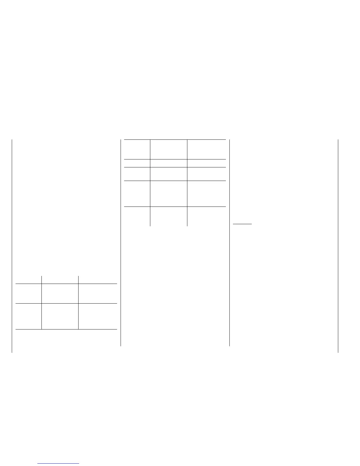
Value Explanation
Possible settings
OUTPUT CH Output channel
(servo connection
of the receiver)
1 … depending on
receiver
INPUT CH Input channel
(channel
coming from the
transmitter)
1 … 12
MODE Fail-Safe mode HOLD
FAIL SAFE
OFF
F.S.POS. Fail-safe position 1000 … 2000 µs
DELAY Reaction time
(delay)
0.25, 0.50, 0.75
and 1.00 s
FAIL SAFE
ALL
Save of the Fail-
safe
Positions of all
control channels
NO / SAVE
POSITION Display of the
saved Fail-safe
position
Between approx
1000 and 2000 µs
OUTPUT CH (servo connection)
In this line you select the respective OUTPUT CH (servo
connection of the receiver) to be set.
INPUT CH ( selection of the input channel)
As already mentioned on page 208, the control functions
of the mx-20 HoTT transmitter can be arbitrarily
distributed to multiple receivers, if necessary, or even
assigned to multiple receiver outputs with the same
control function. For example, this might be used in
order to be able to control two servers for each aileron
fl ap or an oversized rudder with linked servos instead of
an individual servo.
Distribution to multiple HoTT receivers, in turn, offers the
advantage of not having to use a long servo cable, e. g.
for large models. In this case, bear in mind that only the
receiver selected in the line "TEL.EMPF." through the
"Telemetry" menu can be addressed!
The 12 control channels (INPUT CH) of the mx-20
HoTT can be appropriately managed through so-called
"Channel Mapping" (channel assignment) whereby
a different control channel is assigned to the servo
connection selected in the OUTPUT CH line for the
receiver in the INPUT CH line. ATTENTION: If, for
example, you have specifi ed "2AIL" for the transmitter
side in the line "Aile/fl aps" in the "Base setup model"
menu, the Control function 2 (Aileron) is already
distributed to the Control channels 2 and 5 for the left
and right aileron. The corresponding INPUT CH of
the receiver, which must also be mapped, would be
the channels 02 and 05 in this case; see the following
example.
Examples:
You would like to control each aileron fl ap with two or •
more servos for a large model:
You would like to control each aileron fl ap with two or •
more servos for a large model:
Assign one of the two standard aileron control
channels 2 or 5 as INPUT CH to the corresponding
OUTPUT CH (servo connections) depending on the
left or right bearing surface.
You would like to control the rudder with two or more •
servos for a large model:
Assign the same INPUT CH (control channel) to the
corresponding OUTPUT CH (servo connections). In
this case, this is the standard rudder channel 4.
MODE
The settings of the options "MODE", "F.S.Pos." and
"DELAY" determine the behavior of the receiver in the
event of a failure in the transmission from transmitter to
receiver.
The setting programmed under "MODE" is always based