260
Detail program description - Control adjust
Example 2 …
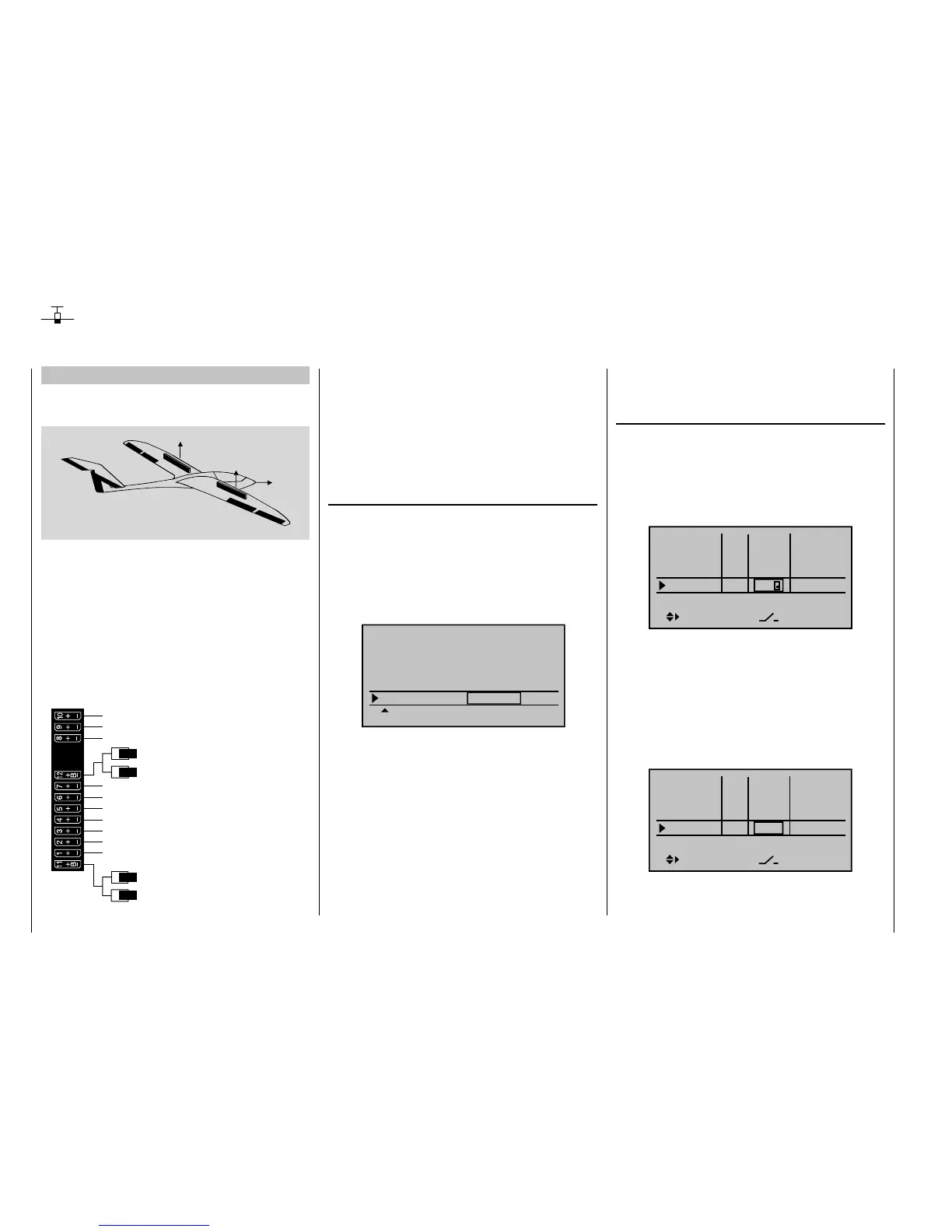
Glider with four fl ap wings, two large fl aps and tow
coupling
AI
FL
FL
AI
EL
RU
The following example is based on the assumption that
you have already mechanically preadjusted the model
and you have already ensured the correct defl ection of
all rudders or checked this again in the scope of this
programming and made adjustments, if applicable,
through servo switching at the receiver and/or through
the "Servo setting" menu.
This programming example is based on an assignment
of the receiver connections in accordance with the
following diagram:
Receiver power supply
Free or aux. function
Free or aux. function
Aileron or left aileron
Elevator or left rudder / elevator
2nd airbrake servo or 2nd elevator or aux. funct
Receiver power supply
1st airbrake servo
Right aileron
Flap or left flap
Right flap
Aero-tow release or free or aux. function
Free or aux. function
Rudder or right rudder / elevator
Begin with the new programming of the model in a free
model memory location.
In the menu "Base setup model", connect your receiver
to the transmitter, enter a model name and select or
check, if applicable, the stick mode. Later, before the
fl ight operation, also activate the range test in this menu.
In the menu …
"Model type" (page 82)
… leave "Motor to C1" at "None" and the tail type at
"Normal". In the "Aile/fl ap" line, on the other hand, set "2
AIL 2 FL".
In the "Brake" line, program or leave "In1", because the
brake and spoiler fl ap servos connected to 1 + 8 should
be activated later with the corresponding C1 joystick as
the control:
Tail type
Motor at C1
Normal
None
Aile/flaps
2AIL2FL
M O D E L T Y P E
Brake Off In 1+90%
SELSTO
The setting in the "Brake offset" value fi eld defi nes
the neutral position of all mixers of the "Brake settings
submenu of the "Wing mixers" menu. Place this neutral
point at approx. +90%, insofar as the brake fl aps should
be retracted in the front position of the C1 joystick. The
remaining path between +90 % and the full throw of
the joysticks, +100 %, is then assigned as idle travel.
This assures that the rudders or fl aps addressed by
the mixers of "Brake settings" remain in their "Normal"
position, even with slight deviations from the limit
position of the C1 control. At the same time, the effective
control path is automatically spread to 100 %.
In the menu …
"Control adjust" (page 96 )
… assign a switch to Input 9, for example, for the
operation of the tow coupling. In order for this switch
to work independently of the fl ight phase, leave the
standard default "GL" in the "Type" column of this input.
With "– Travel +" you can adjust the control travel for the
switching of the switch:
Input 6
offset
0%
0%
0%
–––
0%
Input 7
Input 8
Input 9
–––
–––
GL
GL
GL
GL
typ
9
By simultaneously pressing the keys of the left
touch pad, the setting in the "Servo display" can be
checked.
Since the C1 control should actuate Servo 8
simultaneously with Servo 1, establish this link through
the menu "Control adjust".
For this reason, also switch to the line before and assign
"Control 1" to Input 8.
Input 5
offset
0%
0%
0%
–––
0%
Input 6
Input 7
Input 8
–––
–––
GL
GL
GL
GL
typ
Ct1
However, please note in this connection, that a non-
linear control curve programmed in the "Channel 1
Use of fl ight phases