216
Detail program description - Control adjust
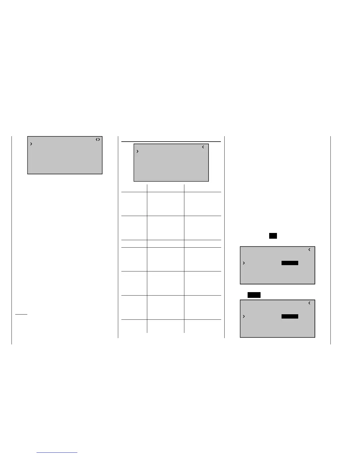
RX CURVE
TYPE : A
CURVE1 CH : 02
TYPE : A
CURVE2 CH : 05
TYPE : B
CURVE3 CH : 04
Otherwise, the left and right ailerons have different
control characteristics.
With the RX CURVE function you can manage the
control characteristics for up to three servos:
CURVE 1, 2 or 3 CH•
Select the desired control channel (INPUT CH) of the
fi rst servo.
The following setting in TYPE only pertains to the
channel selected here.
TYPE
Select the servo curve:
A: EXPO = -100 % and DUAL RATE = 125 %
The servo reacts strongly to movements of the
joystick around the neutral position. As the rudder
throw increases, the curve becomes fl atter.
B: Linear setting.
The servo follows the joystick movement linearly.
C: EXPO = +100 % and DUAL RATE = 70 %
The servo reacts weakly to the joystick movements
around the neutral position. As the rudder throw
increases, the curve becomes steeper.
Notice:
The control characteristics programmed here also affect
the mapped receiver outputs.
RX SERVO TEST
RX SERVO TEST
ALL–MIN : 1000μsec
ALL–MAX : 2000μsec
ALARM VOLT : 3.8V
TEST : STOP
ALARM TEMP–:–10°C
ALARM TEMP+: 70°C
CH OUT TYPE:ONCE
Value Explanation Possible settings
ALL-MAX Servo travel on
the "+" side for all
servo outputs for
the servo test
1500 … 2000 µs
ALL-MIN Servo travel on the
"-" side for all servo
outputs for the
servo test
1500 … 1000 µs
TEST Test procedure START / STOP
ALARM VOLT Alarm threshold
of the receiver
undervoltage
warning
3,0 … 6,0 V
factory setting:
3.8 V
ALARM
TEMP+
Alarm threshold for
excessively high
temperature of the
receiver
50 … 80 °C
Factory setting:
70 °C
ALARM
TEMP–
Alarm threshold
for excessively low
temperature of the
receiver
-20 … +10 °C
Factory setting:
-10 °C
CH OUTPUT
TYPE
Channel sequence ONCE, SAME,
SUMI, SUMO
ALL-MAX (servo travel on the "+" side)
In this line you set the maximum servo travel on the plus
side of the control travel for the servo test.
2000 µs corresponds to the full throw; 1500 µs
corresponds to the neutral position.
Make sure that the servos do not overrun mechanically
during the test routine.
ALL-MIN (servo travel on the "-" side)
You adjust the maximum servo travel on the minus side
of the control path for the servo test in this line.
1000 µs corresponds to the full throw; 1500 µs
corresponds to the neutral position.
TEST
You start and stop the servo test integrated in the
receivers in this line.
By pressing the central
SET key of the right touch pad,
you activate the input fi eld:
RX SERVO TEST
ALL–MIN : 1000μsec
ALL–MAX : 2000μsec
ALARM VOLT : 3.8V
ALARM TEMP–:–10°C
ALARM TEMP+: 70°C
CH OUT TYPE:ONCE
TEST : STOP
With one of the arrow keys of the right touch pad, you
now select START:
RX SERVO TEST
ALL–MIN : 1000μsec
ALL–MAX : 2000μsec
ALARM VOLT : 3.8V
ALARM TEMP–:–10°C
ALARM TEMP+: 70°C
CH OUT TYPE:ONCE
TEST : START